EE BAC Lightning F.53
Royal Saudi Air Force - King Abdul Aziz AB, Dhahran 1977
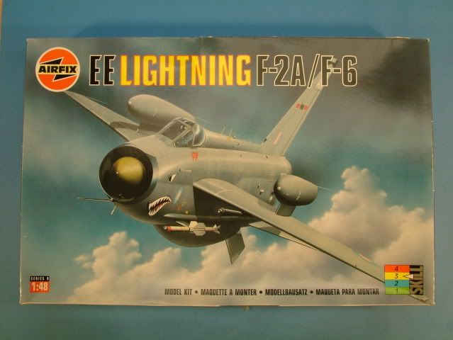
1:48 scale release from Airfix of a BAC EE Lighting F.53, kit number 09178 (OOP).
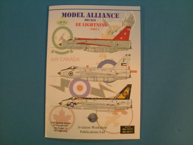
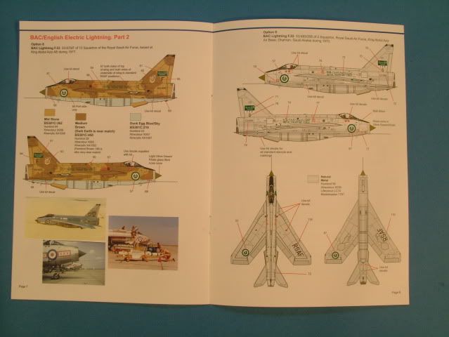
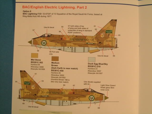
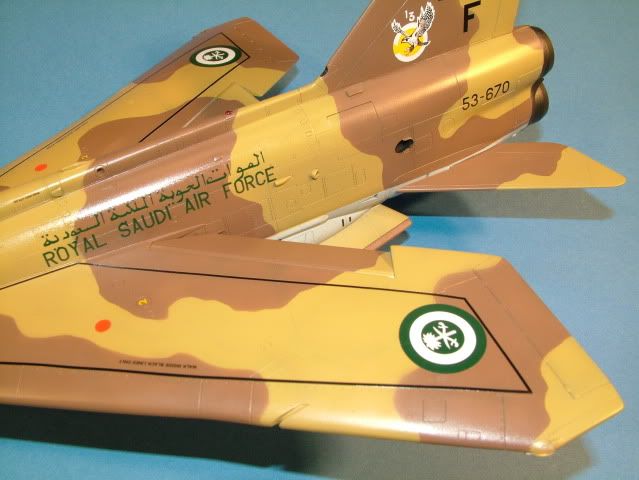
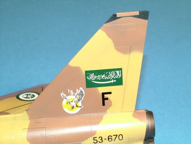
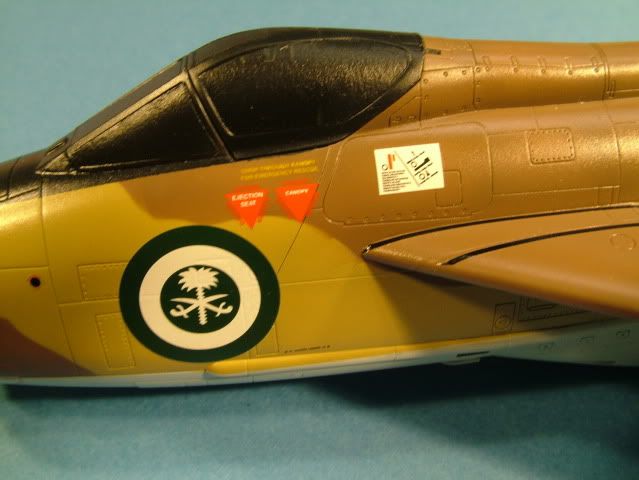
I will be modeling the scheme of serial number 53-670/F which was deployed at King Aziz Air Force Base in Saudi Arabia. The marking for this Evaluation Desert Camouflage Scheme can be found on the Model Alliance Decal Set Part 2.
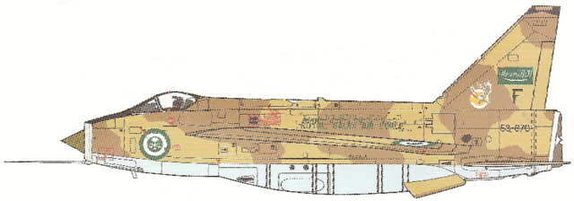
Comments about the planned build:
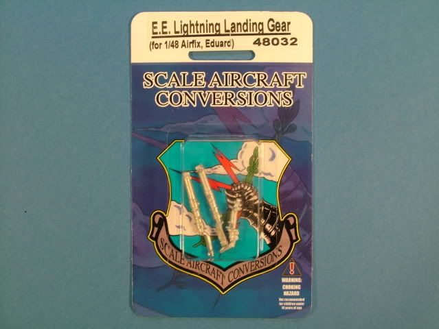
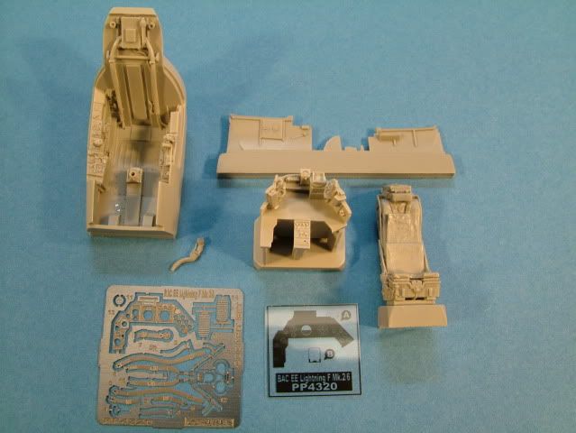
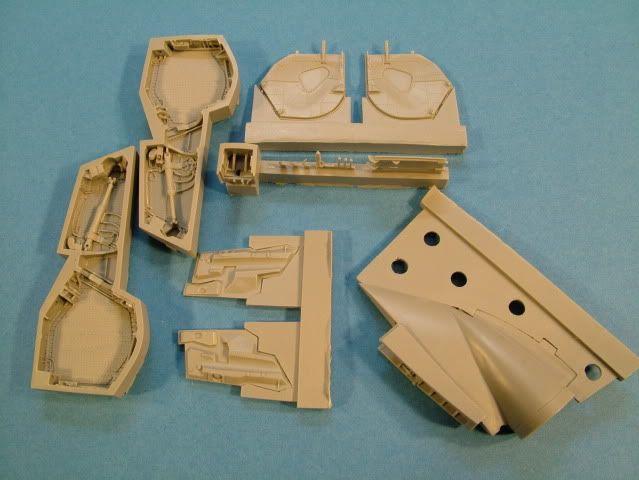
I will be replacing the kit cockpit with the Aires resin version. The wheel wells will be replaced by Aires resin as well. The gear will be replaced with the SAC metal versions in order to increase nose gear weight. Finally the kit engines will be replaced with Aires versions. The kit’s fuel probe and pitot tube will be fashioned out of stacked hypodermic needles.
No over wing fuel tanks are to be installed as I cannot find any documentation that these were used or evaluated in Saudi, even though the capability existed. I will be using the Red Top Missles on the side pylons, eventhough this is an Evaluation Camouflage Configuration for some eye appeal.
Pre-shading to be performed utilizing Tamiya Sky Gray (XF-19) primer coat and a Tamiya Flat Black (XF-1) over the various panel lines and hatches. The camouflage scheme consists of a Mid Stone over Dark Earth. The light Blue underside color is identified as Duck Egg Blue/Sky. A Green/Khaki for the Nose/shock cone Tamiya XF-62 slightly lightened with White. The cockpit interior will be a medium sea grey Tamiya XF-77, NATO Black (Tamiya XF-69) for the anti glare panel. Interior wheel wells and gear to be painted dull silver.
Bits of worn surfaces to be picked out with a silver artist pencil and little dabs of Testors Model Master metallic paint, some boot scuffs on the walk ways to the cockpit will be simulated with a black artist pastel stick, fuel stains on wings and radiator leakage will be simulated with weathering powders from bragdonent.net. Some exhaust staining around and aft of the APU will provide some detail highlights. The exhaust tubes will be detailed with Alclad II and weathering powders from Tamiya.
A clear gloss coat of Testors Model Masters will be applied in preparation for the decals and snuggled down with solve- a-set decal solution if need be. Once the decals have been applied another Gloss clear coat will be applied to seal the decals in completely. Decals will be utilized from Model Alliance and Barracuda Cals for the stenciling. The next step will be to apply ProModeller clay based washes (Dark Dirt) to accentuate the various panel lines and general soft weathering of the Two Tone Desert scheme. As this camouflage scheme was only applied for a short evaluation period, I will keep the pre and post shading subdued and general wear and tear as well.
Kit used:
- Airfix kit number: 09178
Paint Used:
- Tamiya Acrylic, Mr. Gunze, Testors Model Master Metalizer and Alclad II
References & aftermarket products used:
- Model Alliance Decals: The Aviation Workshop
- Barracuda Cals: Barracuda Decals
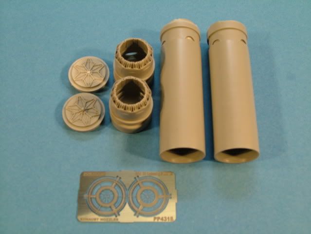
- Aires Cockpit, Wheel Wells and Exhausts: Aires Reviews
- SAC Metal landing Gear: SAC Gear
- Weathering Powders by: bragdonent
- Federal Standard Color Chart: Official FS Chart
A special thank you again to Mike Smith & Fred at Colpar Hobbies for their kind and endless support while searching and chasing various aftermarket vendors whilst locating all the “bits and pieces” that make up my builds.
Tools used:
-
- Delta Electric variable speed Disk Sander – used to remove casting blocks for Resin
- H&S Evolution 2 in 1 Airbrush
- Badger 100 LG Airbrush, Medium, Fine & Extra Fine tips
- Dental Tools for scribing panel lines , P Cutter & Scalemodelsport.com Scriber
- JLC Razor Saw
- RB Productions Riviting Tool
- Xuron Sprue Cutter
- Small curved scissors
- X-Acto Scalpel blade(s)
- The “Bug” PE bender
- Pin Vise
- Pin drill bitts
- Cocktail sticks
- Cotton Buds (lots)
- Scribing Templates
- Tamiya Masking Tape various sizes
- Various sanding sponges from MDC & ProModeller.com
- Bow Sander by Flexifile
- Parafilm for cockpit glass masking
- 3-M White Tack for masking off wheel bays, intake and engine exhausts
- Lead Wire – ballast inside the nose cone
-
Glues & Putties used:
- Zap Super Glue medium thick
- Zap Super Glue Kicker
- Tamiya Extra Thin and Thick Cement
- Gator Glue by Gator Grip
- Mr. Surfacer 500 and 1000
- Mr. Surfacer 1200 Spray Can
- Polly Scale – Plastic Prep
Paints Used:
- Tamiya XA-20 Thinners
- Tamiya XF-1 Flat Black
- Tamiya XF-2 Flat White
- Tamiya XF-3 Flat Yellow
- Tamiya XF-7 Flat Red
- Tamiya XF7 – Gloss Red
- Tamiya XF-10 Flat Brown
- Tamiya XF-19 Flat Light Grey
- Tamiya X- 25 Clear Green
- Tamiya X-27 Clear Red
- Tamiya XF-69 NATO Black
- Tamiya XF59 Desert Yellow
- Tamiya XF-52 Flat Earth
- Tamiya XF-77 IJN Grey
- Tamiya X-23 Blue
- Tamiya XF-62 Olive Drab
- Alcad II Aircraft Aluminum
- Alclad II Aircraft Steel
- Model Master Gloss Lacquer – Decal prep coat
- Model Master Semi Gloss & Flat Lacquers – Final sealing coat
- Micro Sol & Set decal solutions
- Future - for cockpit glass and instrument gauges
Final detailing:
- Promodellers Dark Dirt Weathering Wash
- Bragdonent weathering powders
- Tamiya Weathering powders Master set C&D
- Gallery “artists” soft Pastels
Box Art:
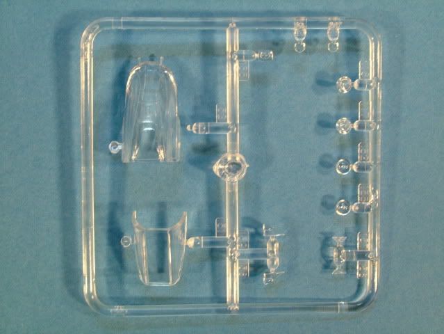
Sprue Shots:
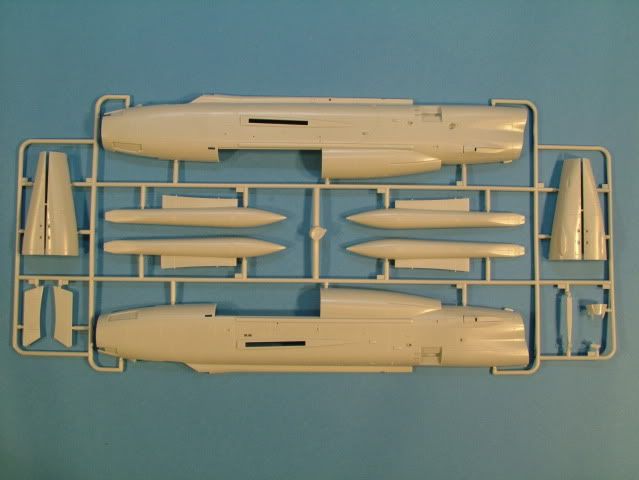
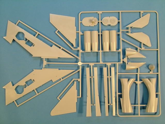
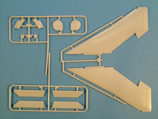
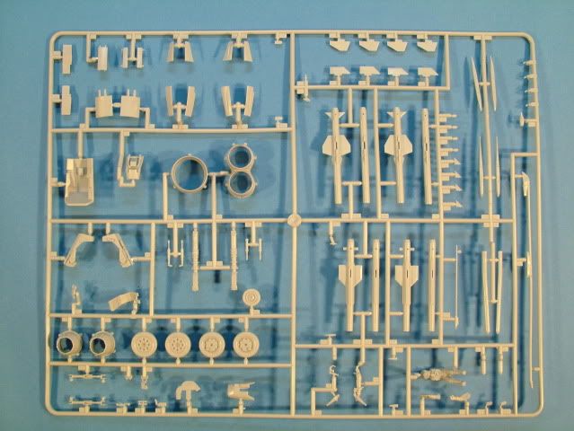
SAC Metal Landing Gear:
Aires Cockpit Set:
Aires Wheel Bay Set:
Aires Engine Set:
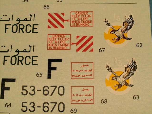
Model Alliance Decal Set:
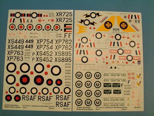
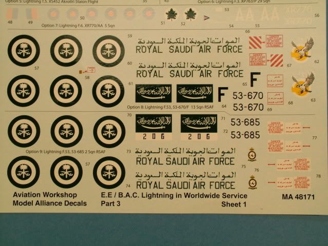
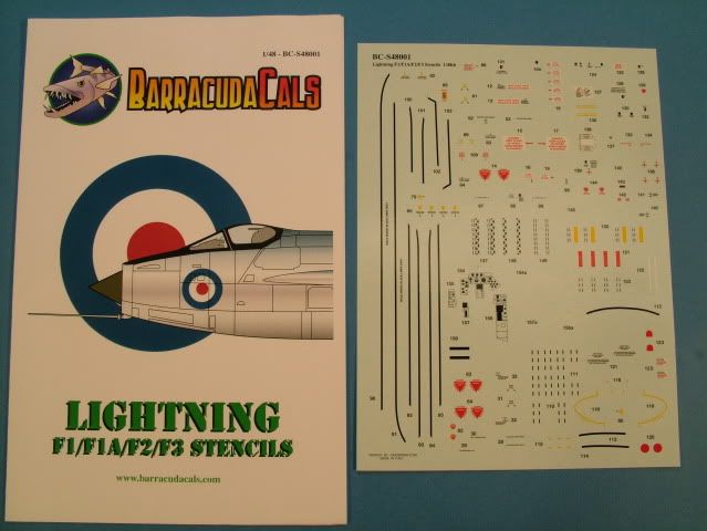
Barracuda Cals Decal Set:
Instead of working the cockpit, thought I would start with something "simple".
First step is to remove the kit interior wheel well walls. I used a sprue snipper and then sanded down all the way to the top (inside/bottom) of the wing.
Bottom one is complete, top one for comparison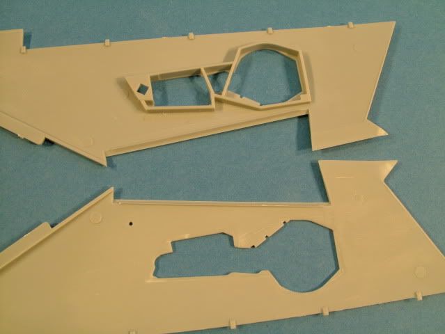
Now comes the hard part, somehow to get the the inside of the top half of the wing thinned down.
In order to get a feel for where I needed to scrape I used a red sharpie to outline the area.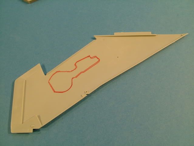
Using a X-acto curved blade I moved cross hatch wise over the area until I got to "paper thin".
Also removed the casting block and got the resin to paper thinness. furthermore had to sand down the opposite side of the wing to get enough space to insert.
Just use patience and caution, checking every few minutes against a light to see how much material you remove.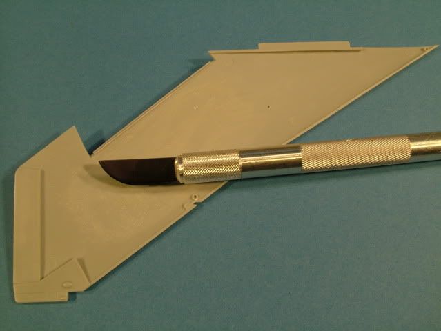
This side was sanded with a short piece of aluminum bar with sticky back sandpaper and ensured I had just enough room and keeping it flat.
It also makes the area more scale like where it butts up to the wheel well.
Did quite a bit of reading on other builds found on the Internet, it appears that the front slat area is a bit of a tricky fit.
The instructions Airfix would make you glue on the two wing halves first and then install the front slat piece.
Used small pieces of white card stock styrene to strengthen and to ensure the slat is tight against the wing and straight without any nasty habit of "wobbles".
Tamiya Thick glue was used as to get good strenght and (in my findings) does not have as much of a tendency to attack (deform) the plastic when you deal with very thin stock as compared to using the thin type.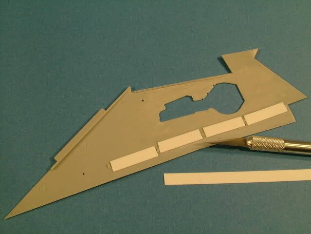
Then the moment of truth, placing the resin well against the opening, traced carefully around with a red sharpie and made sure I aligned right on with the opening.
Then a small bead of thick super glue was applied and smeared out with a cocktail stick so no oozing was possible, glued on the well.
After another check I placed a small bead around the well for strength. (The square hole you see is for the landing gear to be installed into).
If you look closely you can see how Paper Thin I did get. Oh so close... check the few tiny little prick holes towards the top.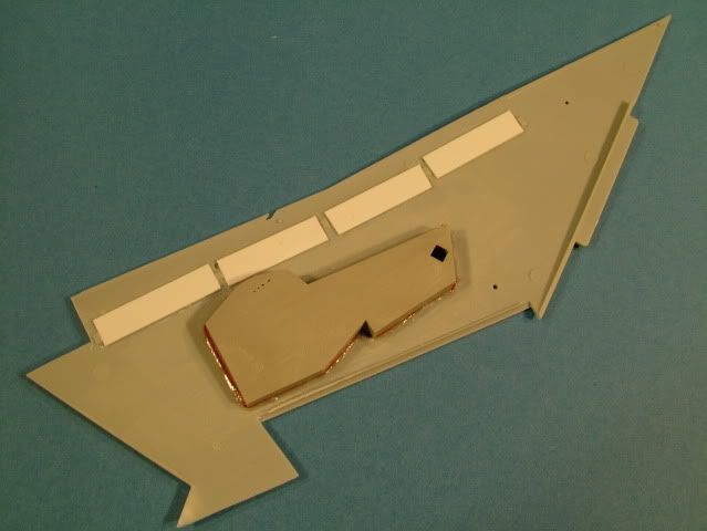
All in all this was quite a bit of work (5 hours of fiddling, fitting, figuring out sequences, sanding and the like). Was it worth it? Here are some comparison pictures (Aries top, Airfix kit bottom).
Please use caution to NOT glue the top of the Aires Wheel Well to the inside of the top wing half. If you do ... you will deform the original wing shape. ONLY glue the wheel insert to the bottom wing inside half.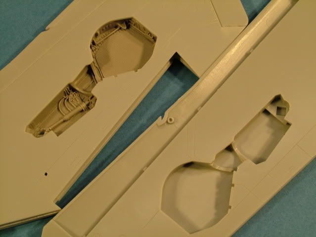
Here is the Airfix kit bare version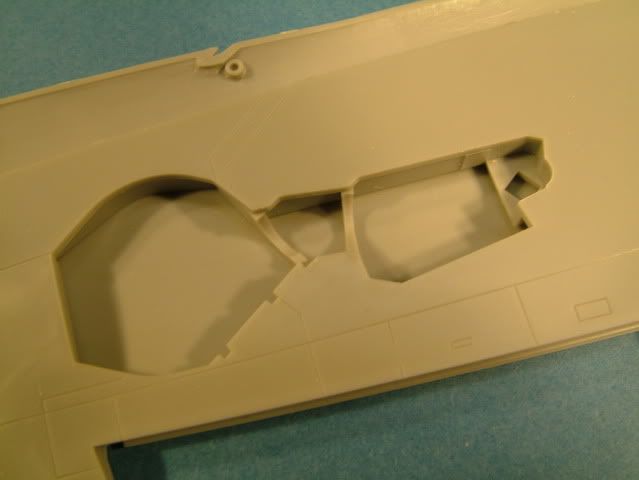
Aires Wheel well inserted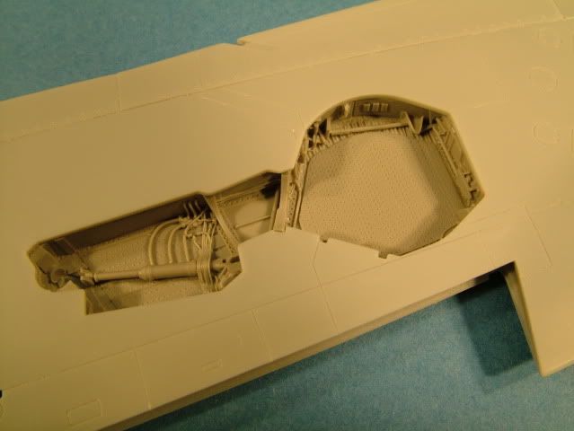
The lower wings halves had some box damage at the very sharp tip (this boxing was probably stored for 5 years somehwere and tossed around quite a bit.
The damage to the bottom wing half tip was easily fixed by warming up the plastic and bending straight and a little dollup of super glue hardened with kicker and then sanded into correct shape.
One other usefull tip is I used a little white tack where the lower wing half matches up to the aileron to "lift" it up and align correctly. Hope this makes sense....once you get to this step.
Still need to insert a strengthening plate of white styrene where the flaps go.
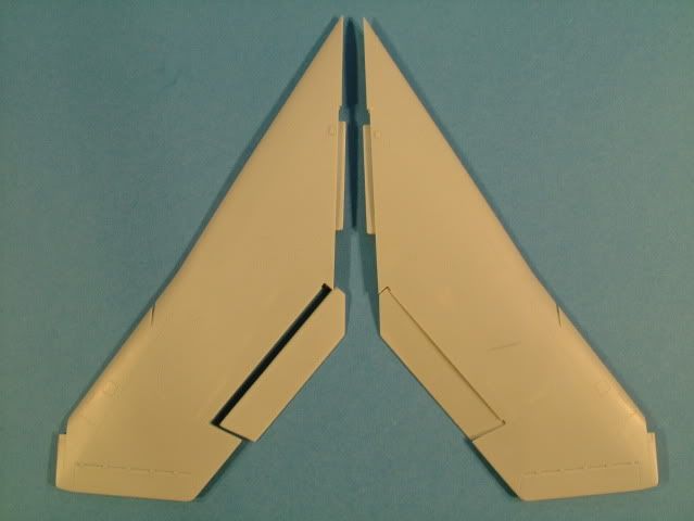
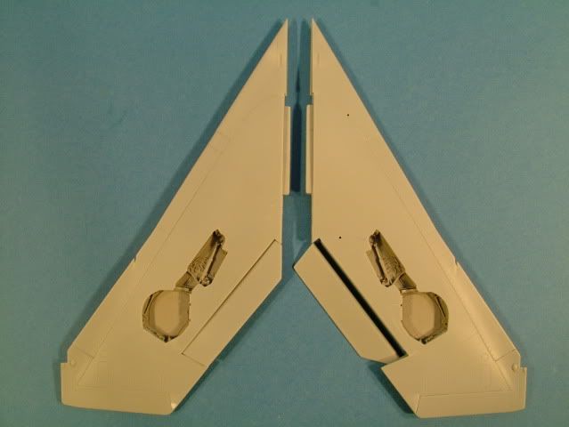
tiny bit of re scribing at the leading edges but that's all. Primer will tell all in later steps.
I am approaching this build a little different as there is quit a bit of prep work in various areas due to the large amount of aftermarket additions.
Working the Nose Shock Cone and associated Nose Wheel Bay next.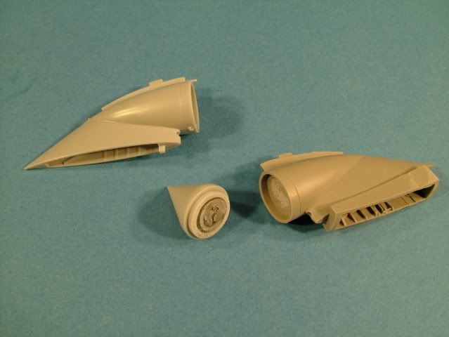
Built up the kit version too as I will use it to figure out how things where supposed to line up before making adjustments for the resin pieces.
Inserted pieces of lead wire in the shock cone for extra weight. Airpockets filled with super glue and then sanded smooth.
Showing alignment of original kit part vs the Aires insert. The kit shock cone fits extremely well, and just polished the join that's all.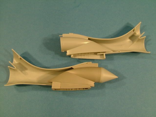
Remove of the lower kit wheel bay detail is required and cut back a little to allow for the resin to "sink" through.
Clean up of the ejector pin marks on the inside of the air intake.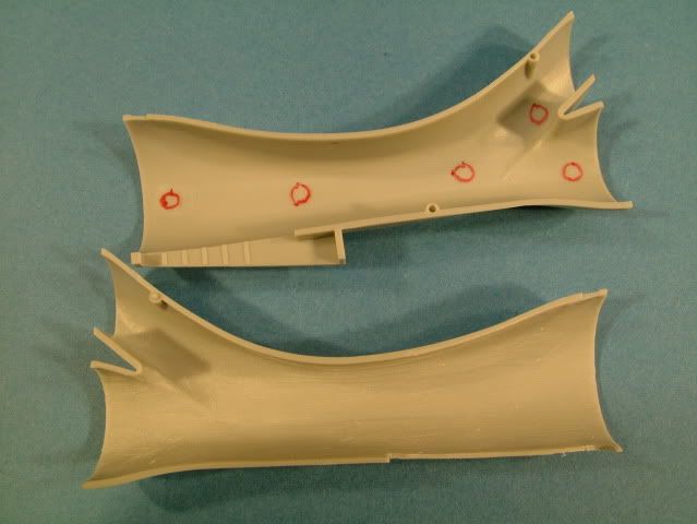
They are quite obtrusive, not so sure you will be able to see them, but I always use these as a great exercise to hone my skills.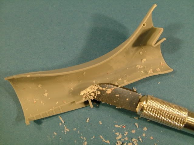
Using the rounded tipped X-Acto they remove pretty easily
I also removed the alignment pins.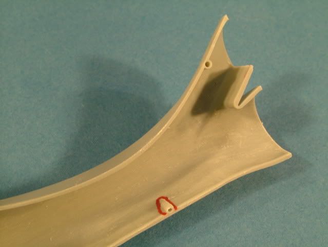
Here is the material marked that should be removed.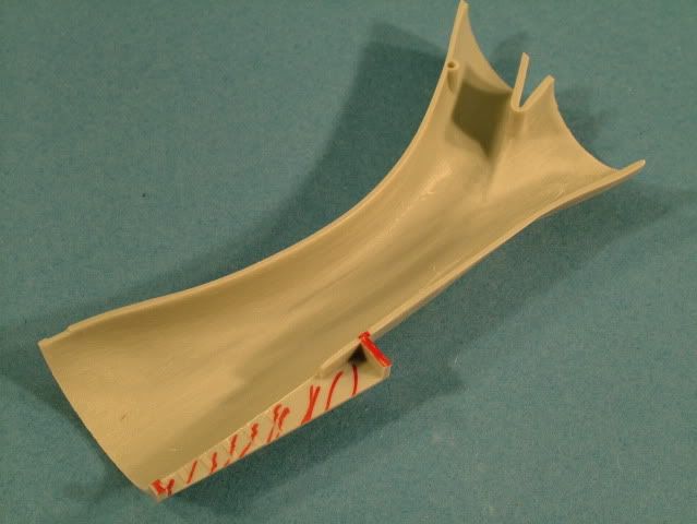
A little light sanding will take care of smoothing out the intake.
Parts dry fitted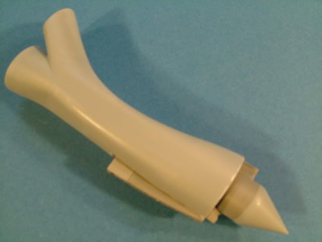
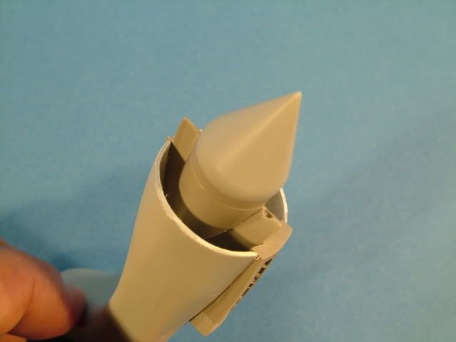
Next step was to work the Fuselage (Deviating again from the normal build sequence of installing the gun bay belly after the fuse is glued together).
I believe my approach will result in a better overall fit and strengthened join.
First up I needed to build up slightly a potential gap at the front piece. 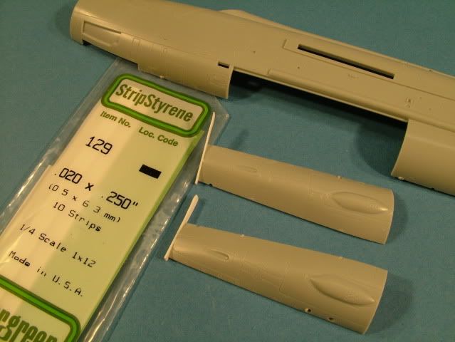
Some thin white strip styrene is used to build up the section, then cut and sanded to shape.
Last step is to carefully sand back the thickness added to "fill the gap"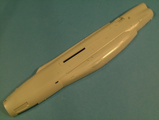
Smooth as silk, nice joins and no filler used anywhere.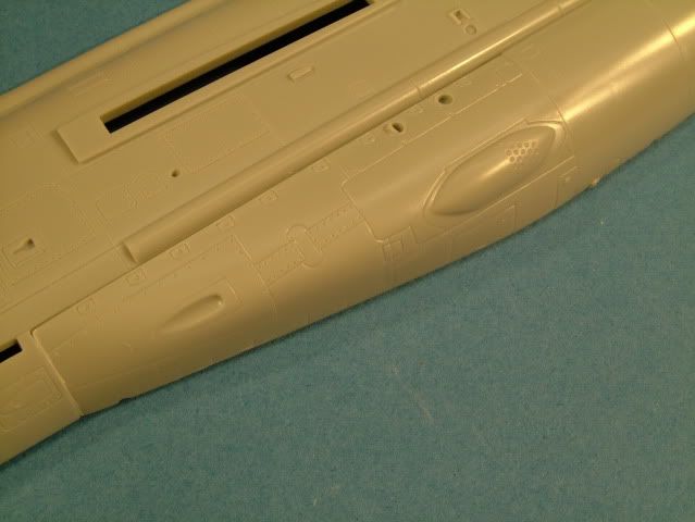
Glued in some white strip styrene to strenghten and align the far aft join.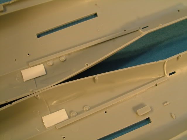
The air brakes will be shown in closed position (I have only seen one Lightning picture immediately after landing that shows them in open configuration)
I used a little white tack to bulk up and fill the gaps below the air brake cover as to improve the alignment with the fuse and not cause any "hollow ---sunken---look"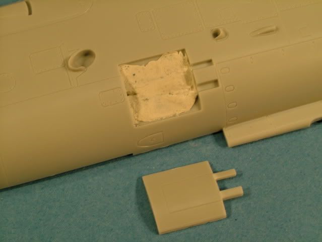
Next started drilling out various vents and will work the large APU with a piece of Brass rod.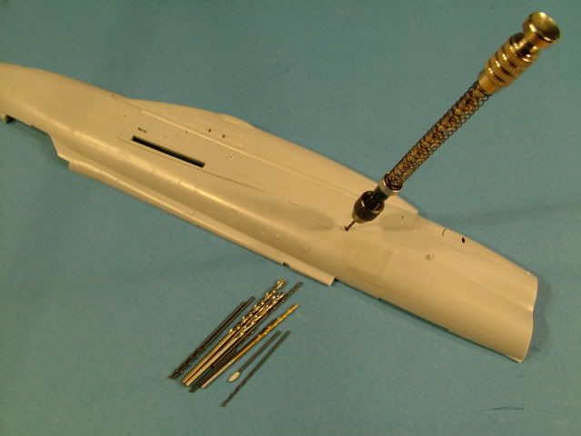
drilling out the wheel hubs.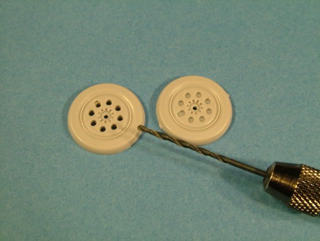
Cleaned off the MINOR flash from the SAC Gear and polished up to a lovely shine.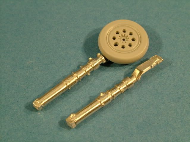
Time to figure out how to make the cut on the kit canopy assembly.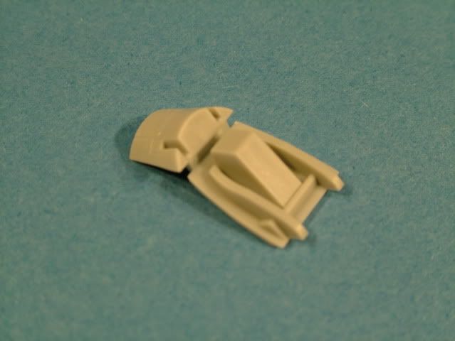
Aires instructions carefully checked and double checked. Make sure you cut from the bottom straight across.. (You can if you follow the instructions to a "T" leave the little stub on it. However while final fitting I discovered it is not required for a tight fit).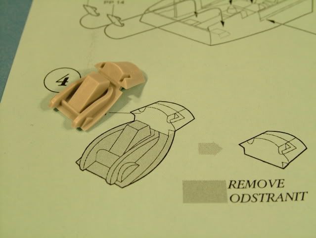
Parts separated with my JLB razor saw and a slight careful sanding.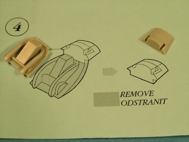
Cleaned up all the casting blocks from the cockpit parts with the JLB Razor saw and sanded off the bottom of the cockpit casting block with an electric disk sander.
The whole cockpit was airbrushed with Tamiya XF-77 (Dark Grey) for other parts this is a great color for priming them.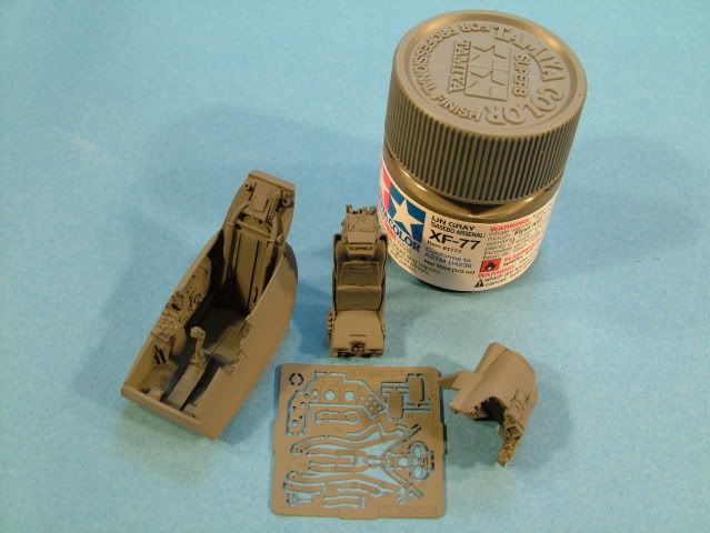
The air intake was sanded down, painted with Tamiya flat White as a primer/filler, then sanded down again.
Airbrushed on a, thick double coat, of Tamiya Gloss Black in preparation of the Aluminum.
The shock cone and the nose wheel well was treated the same way.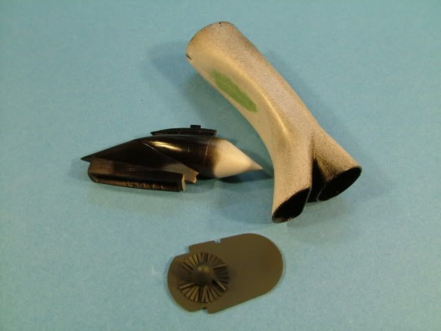
The turbine blades were slightly dusted with some Alclad Silver to allow some shading to appear.
Alclad Duraluminum provides a nice toned down dull shade for the interior aluminum color on the air intake.
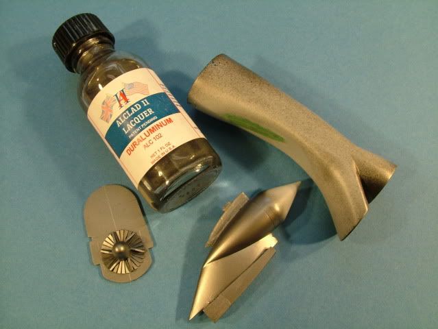
To provide a little "eye candy", cut a strip of Model Master aluminum and applied the strip right behind the shock cone.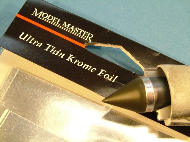
The shock cone was painted with Tamiya Khaki Drab XF-51 25% to Tamiya Olive Drab XF62 75% thinned to 50/50 paint to thinner to get a nicely weathered "Green" look.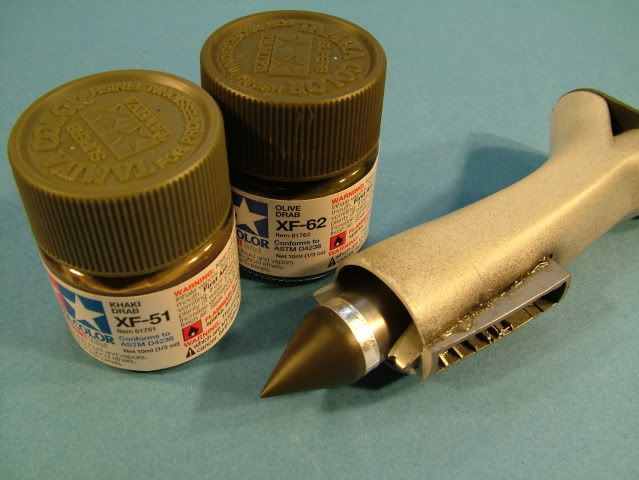
The cone and nose wheel bay assembly was then carefully inserted, checked multiple times again for alignment.
Then glued with super glue and a little kicker to hold a "round" shape while comparing to the outside nose intake lip.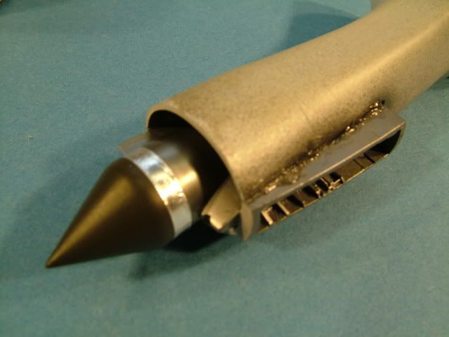
Whilst I had my airbrush loaded up with Alclad, I also airbrushed the main wheel bays.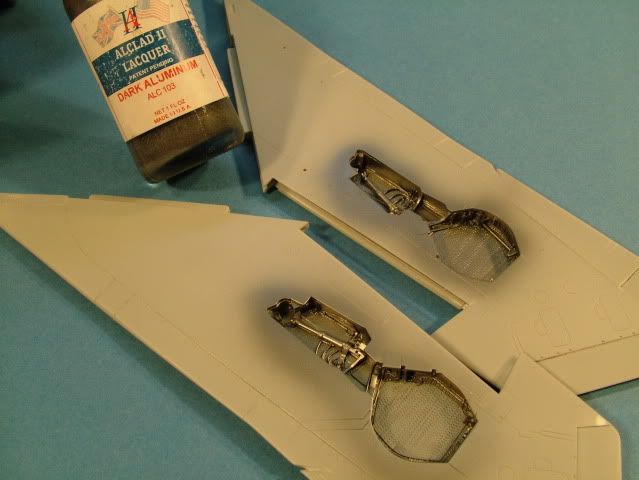
Spent quite a few hours (repeatedly) dry fitting this assembly, whittling and sanding down the cockpit side walls.
Patience is key here and will pay off in the long run.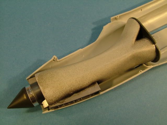
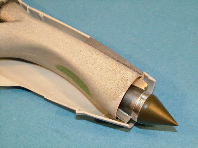
More dry fitting and ensuring no interference anywhere between cockpit bottom and the air intake, whilst ensuring we line up the cockpit coming.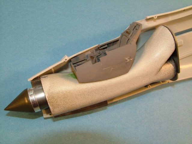
Dry fit and checking "centering" of the cone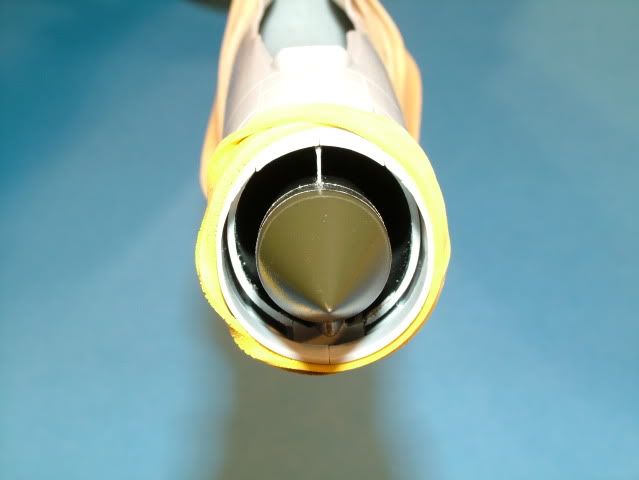
Dry fitting whilst checking for alignment of the nose gear front and rear wall and keeping center on the shock cone.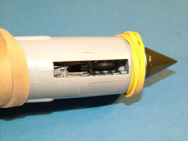
Dry fit check on the cockpit side walls and coming. Bottom side is nearly there, top one un-touched for comparison.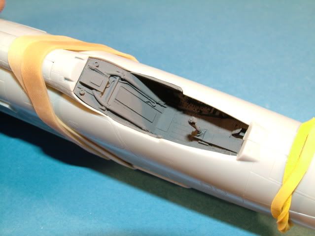
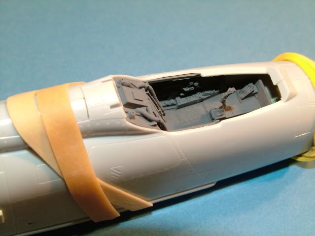
Here is that "little" canopy assembly again.
So far all aligns well without stressing the plastic anywhere or pushing things out of kilter.
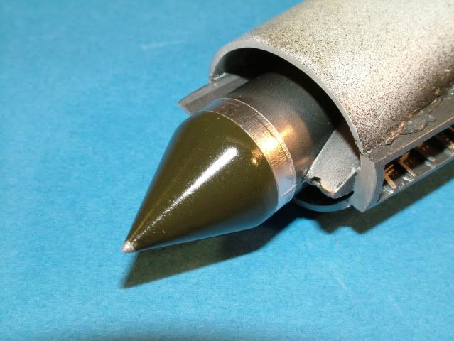
Scribed a small ring around the far edge of the shock cone and used that to
align the little silver tip.
A gloss coat from Model Master protects the paint finish until the final weathering stages.
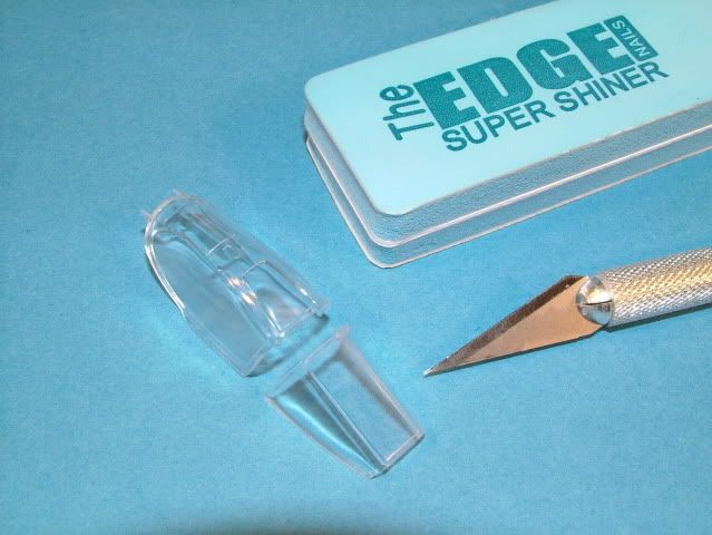
Cleaned up the canopy flash and polished up the canopy with various grit sponges from MDC.
A little light final polish with the Super Shiner until it squeaks ensure a crystal
clear start for the upcoming step of the Future bath.
This canopy does not have a seam down the middle so a light touch is all it
takes for the clean up.
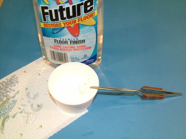
The front armored glass and the canopy were dipped into Future and then
placed on a paper towel to allow the excess to draw away from the parts.
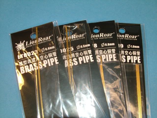
Using some brass pipe from Lion Roar found a suitable diameter to simulate the gun. (0.8 mm).
The brass pipe was installed with a little thick Super Glue and kicker.
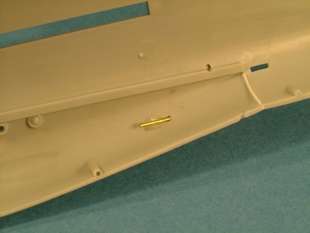
Just a little re-scribing around the panel lines for the gun port and a touch of
thin Tamiya into the panel lines tidied up everything.
The guns are only just poking through a touch to provide some interest into this area.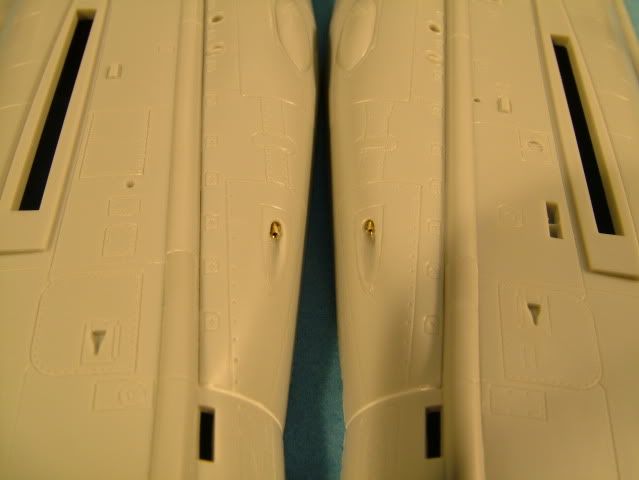
The engine sub-assembly is started next:
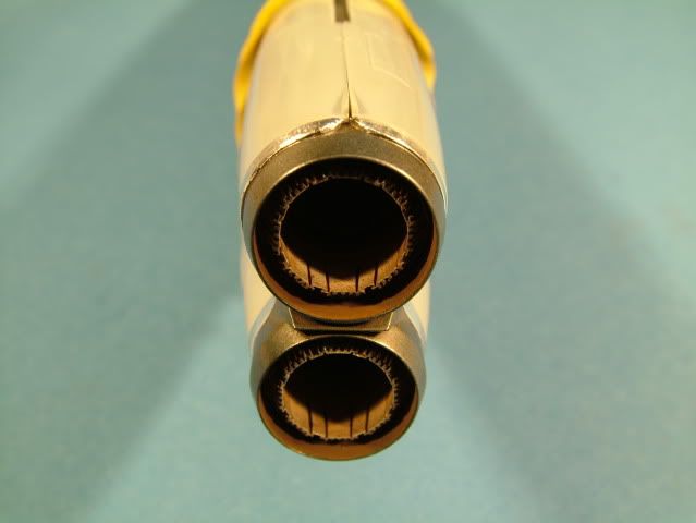
The inside was painted with Tamiya XF-2 flat white, the outsides where
painted with Tamiya X-1 Gloss Black.
A coat of Model Master Gloss seals in the paint and provides a super smooth
finish for the metal work to come.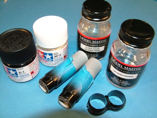
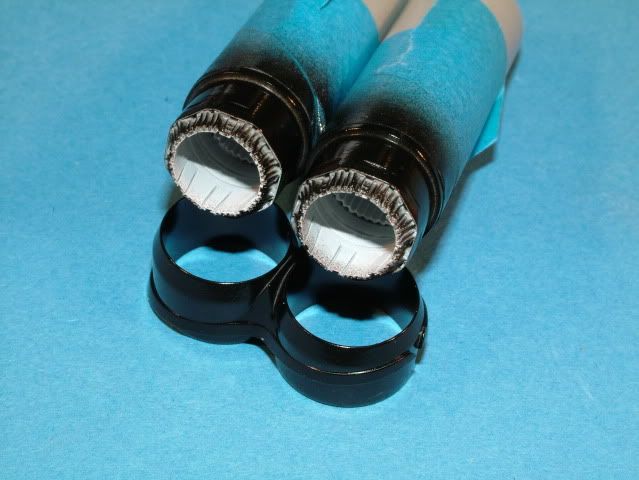
Once dried the outer rings were airbrushed with a light dusting of Alclad Dark
Aluminum and a light dusting of Pale Yellow.
Some very light dusting of Alclad Clear Blue was sprayed from a further distance.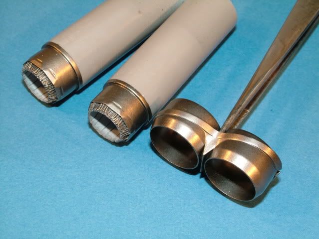
Wrapped a strip of the chrome tape around the edging to simulate a different metal work.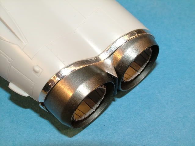
Installation of the turbine fan blades.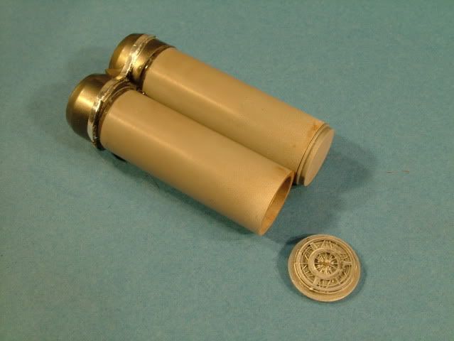
The insides where treated with some "dark" rust and soot from
Bragdonent.com weathering powders and sealed in with a flat coat from
Model Masters.
The next step was to carefully align the exhaust tubes with the back fuse
edge and the rear bulk head.
Utilizing a small blob of White Tack in between the tubes and the inside fuse helped keep everything in place whilst checking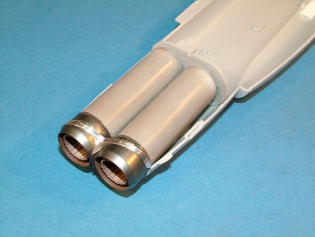
When satisfied glued on the rear bulkhead with some Super Glue to the rear
of the resin backs.
The rear bulkhead is NOT glued to the inside of the fuse half at this stage.
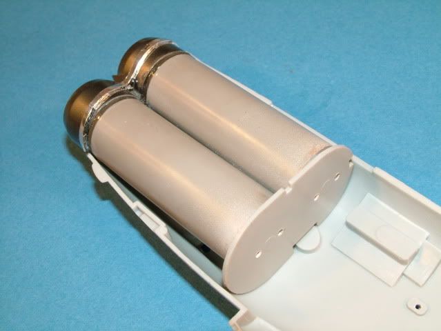
A check for alignment between the two fuse halves is performed to ensure all fits perfectly.
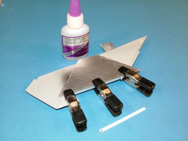
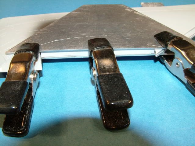
In order to get a straight trailing edge for the flap to mate up to, used two small steel edges.
These were clamped top and bottom and the a small strip of white styrene was inserted.
The strip styrene will ensure a strengthening of the wing here as it is quite thin.
This was glued in place with some thick Super Glue and some kicker to set it in place.
The next step is to close off the small gap at the ends.
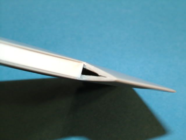
Again some white strip styrene was glued and then sanded following the airfoil.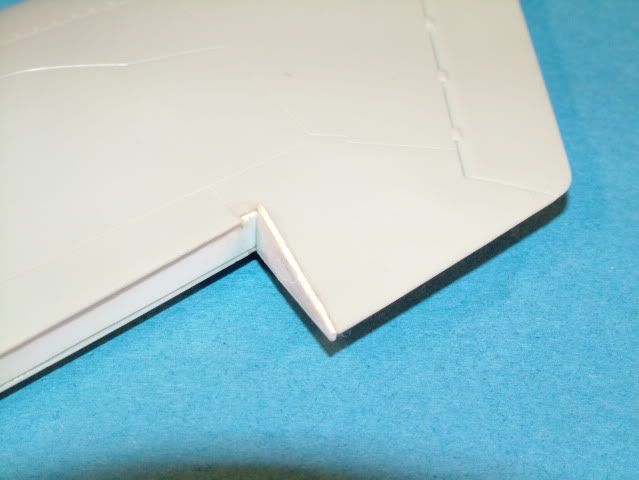
The flap leading edge was slightly sanded flat at an angle in order to give some mating /gluing surface.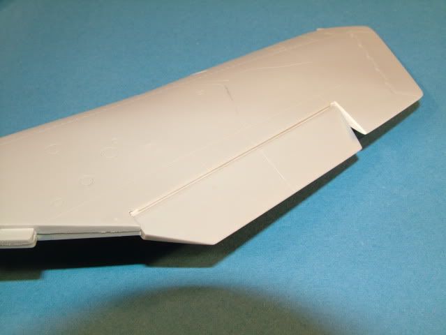
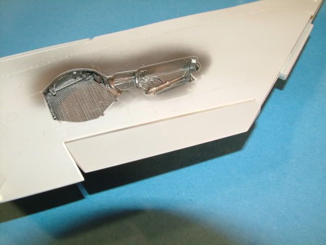
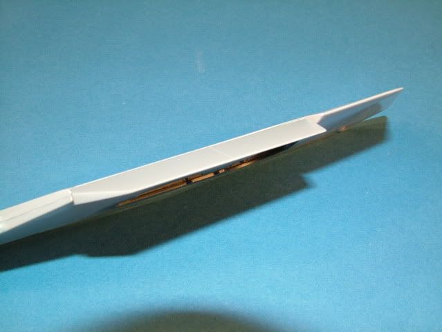
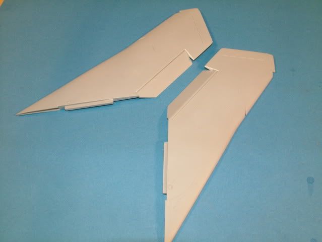
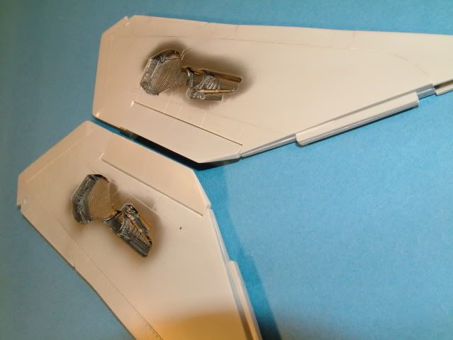
A little effort in scratch building and these look much improved, plus provide for a rigid straight wing.
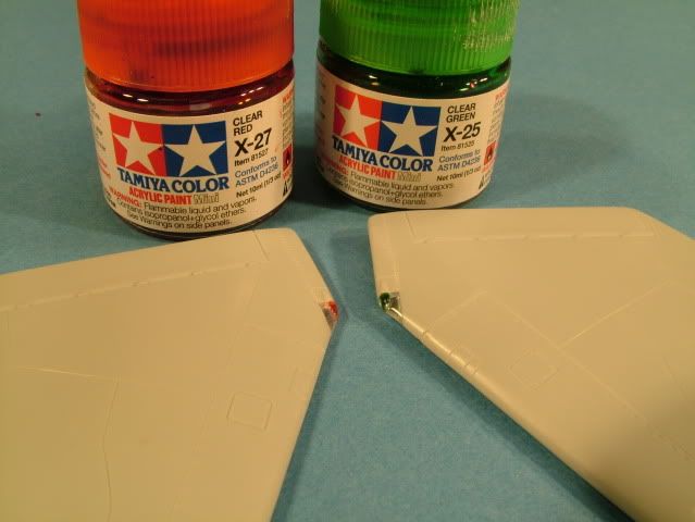
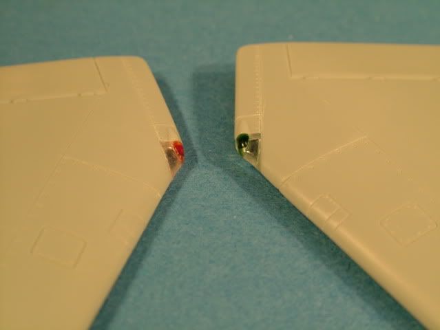
Finalized up the tip navigation lights on the wing.
-
Drilled a small hole from the backside into the clear plastic
-
Dropped in some Clear Red and Clear Green with a cocktail stick
-
Let paint dry
-
Some final initial fitting, then glued with Thick Super Glue
-
Sanded down and into the wing contour the Clear lens
-
Polished up with the Super Shiner and some Novus Plastic polish
-
Re scribed the panel lines around the Wing Tip light
-
Placed some small rivet's where detail was lost with a dull tipped needle
-
Polished up the area of all the re-work.
-
Just have to mask off the actual tip light with some liquid mask all when painting starts.
Hope the detail can be seen, used Tamiya Clear Red X-27 and Clear Green X-25
Pitot tube is detailed out
- The kit one appears to be flattened somehow, according to ref pictures this is indeed a "tubular shape" however.
-
Found two suitable brass tubes from "Lion Roar" 1.0 mm and 0.8 mm
-
Cut the plastic "mis shapen part" away from the attachment location bump
-
Cut brass tubing to correct length
-
Stack tubes and glue with superglue
-
Drill small hole (1.0 mm) into plastic "lump"
-
Slightly taper brass tubing to be inserted into the lump
-
Glue with superglue
Before: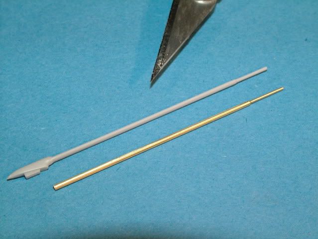
After: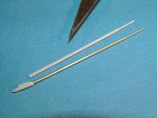
I made one more "little" cool detail, I used some lenses from Little Cars and inserted it into the nose cone intake location.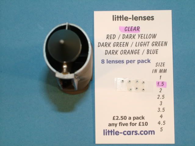
You can see the glow from the flash in the light in this picture.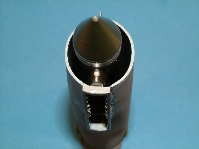
Just some primer around the cockpit and exhaust area and check for any mistakes.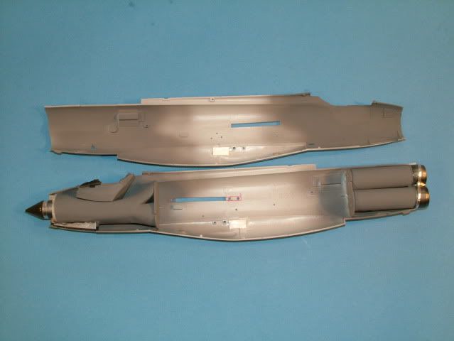
Performing a final dry fit, including the plastic nose ring (the metal one will be making it's way shortly- thanks again Marcus).
The clear canopy is in place .. loosely fitted.
Double checking that nothing is getting stressed or pushed out of normal kit alignment after inserting all the resin parts.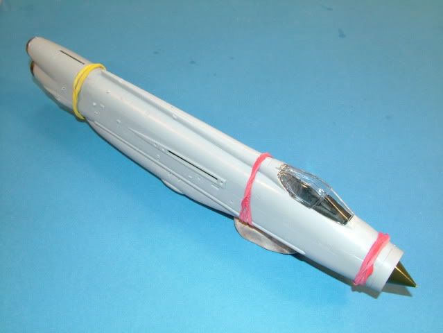
Checking for canopy frame to fuse alignment and no lip present.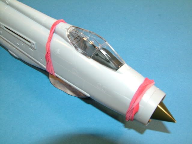
Checking for front armoured glass alignment to the fuse, no interference from the Resin Hud etc.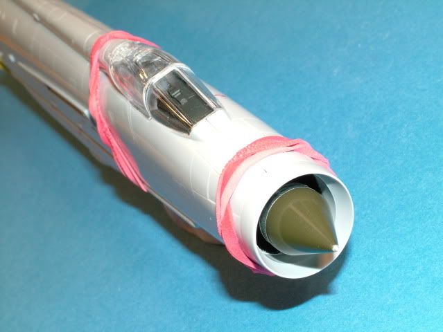
Worked the anhedral of the wing (negative incidence) and the match up to the fuse. 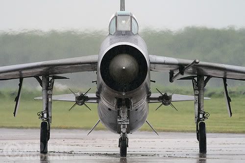
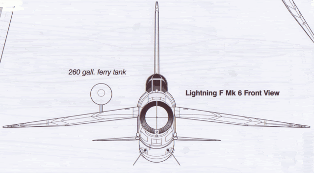
As this is quite a tricky connection/joint, and the overall profile of the model is a key visual component, here is how I decided to solve.
This goes back to my RC-Days where wing alignment becomes quite critical
-
Cut off the plastic alignment tab from the wing area.
-
Sand down the edge and any remaining tab with a steel edge to ensure a perfect flat surface.
-
Double check against the fuse, sand the fuse /join area for the wing if required.
-
Drill two small holes through the fuse and into the wing.
-
Use two small button head screws to temporarily pull the wing tight to the fuse.
-
Measure the negative angle of the wing to the work bench and check against your reference.
-
Sand as required to get correct wing anhedral.
-
Once satisfied, strengthen the holes in the wing surface with Super Glue and let dry.
-
Do this for both wings, before proceding and permanently gluing one side.
-
Install both wings this time and rubber band the fuse together.
-
Use some small pieces of Post It Brand notes with appropriately measured distance from work bench to wing tip.
-
I used the last panel line and two lines per wing to be able to see the washout in the tips as well.
-
Sand any needed angle and ensure both wing panels appear same.
-
Apply Thick Tamiya cement and pull wing back into fuse using the small button head screws.
-
Check the wing angle again.
-
When satisfied apply Thin Tamiya cement to the wing joint and let dry overnight.
-
Sand and polish the join area.
-
Applied a very small amount of Mr. Surfacer and wiped clean with Tamiya thinner on a cotton bud.
-
Checked the join with a light spray of Tamiya paint.
The fin is taped in place and used as a reference point for vertical position of the fuselage.
A leveling triangle was used to verticle align the fin to the workbench (not pictured).
The fuse was "pinned" in place with white tack (not pictured) which lends itself to easy small corrections by pushing it against the fuse when required.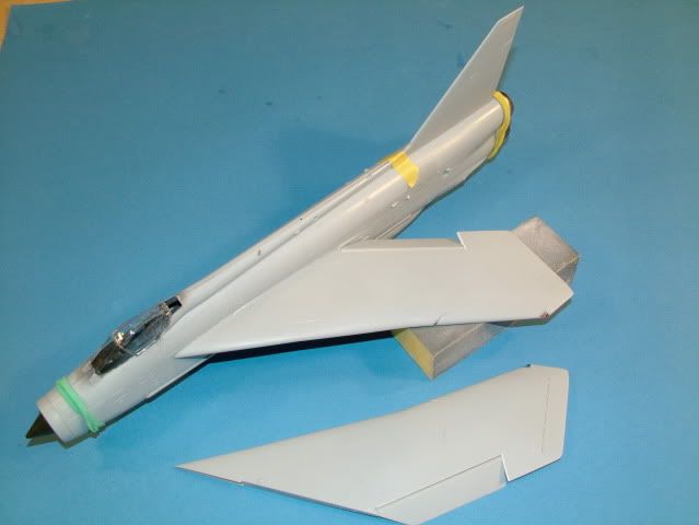
The two button head screws in place, temporarily.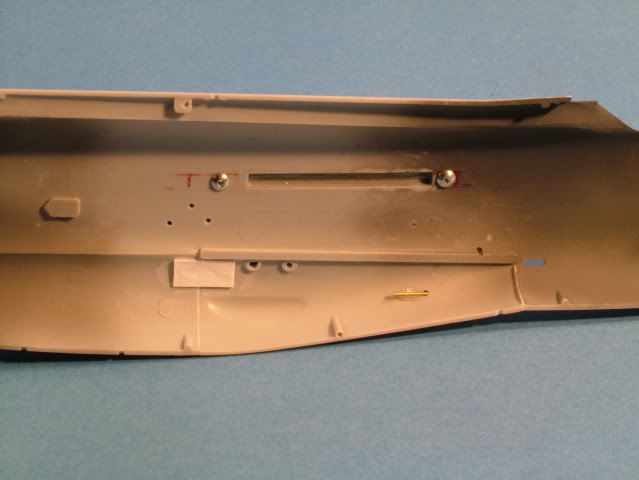
Sanding of the correct wing angle is performed with a small aluminum straightedge with a piece of sandpaper glued to it.
Small sections at a time, dry-fitting, checking, sanding, dry-fitting, repeat.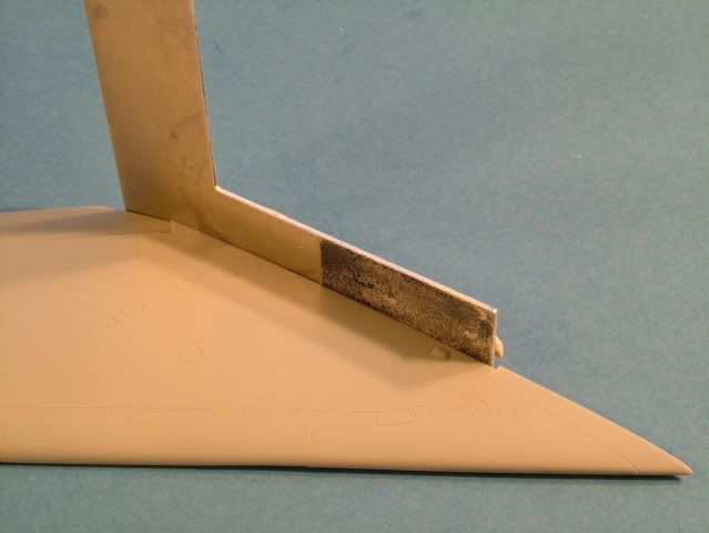
The wing mating surface nice and flat and with correct angle.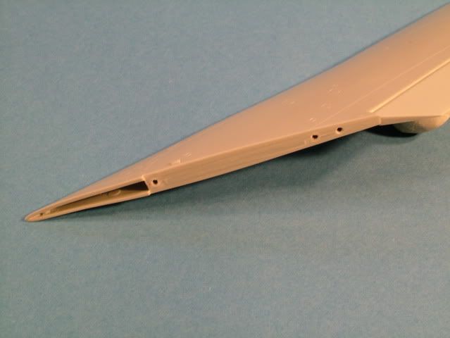
Measurement of the wing tips, the Post It note has been moved only slightly as to depict the idea.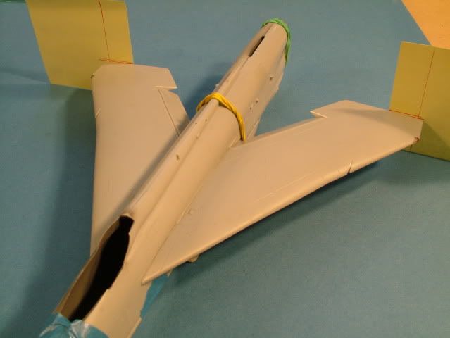
The verticle line is to line up with the last -- furthest out -- panel line (right before the nav light).
This line is also used to eyeball against the main triangle taped to the workbench (not pictured)
The two horizontal lines depict washout of the trailing edge of the wing tip.
Fuse has been disassembled again and the first wing join has been completed.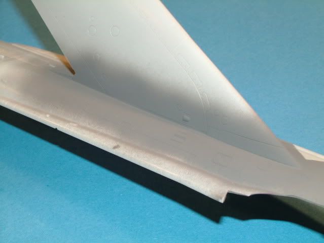
Ejection seat construction and painting:
Here are the base paint colors.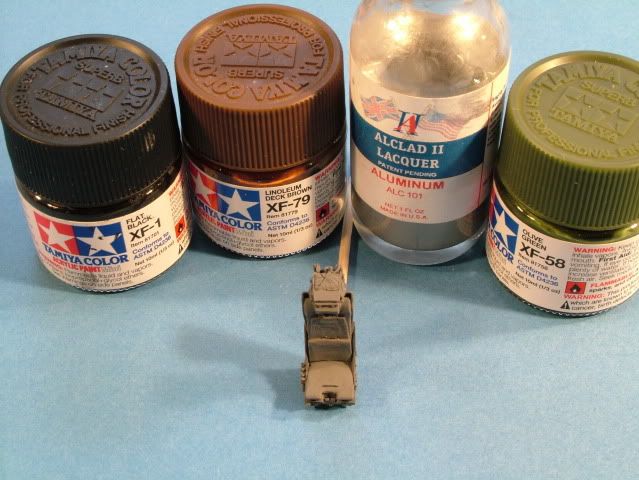
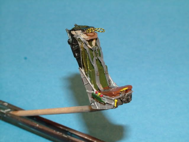
Carefuly scraped off the grey paint from the metal buckles and adjustment connections with the tip of the knife, revealing a nice shiny "buckle".
Reference Picture used. Not sure if I should go back and change the color of the main harness from Grey to a "Khaki".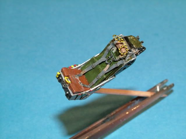
Still a bit more to go on the (lap) belts and a pin wash, then the decals, sprayed some semi-gloss to "glue" the belts in place after they
were tacked with Super Glue.
Final coat will be a flat finish except for the aluminum seating pan.
The nice overhead Pull Handles are from JTGM (Another Forum Member), wouldn't know how to build without these now. 
Here are all the colors used.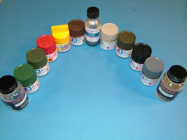
Used thick super glue and kicker to set the glue in place whilst holding the correct shape and lined up the inner walls of the intake.
A shot of kicker ensured a rapid cure of the glue.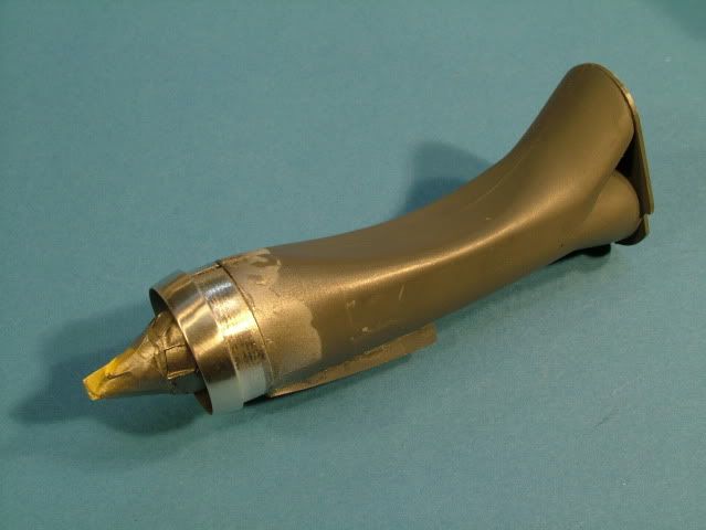
I sprayed another light layer from the front into the intake of Alclad Dark Aluminum to ensure no exposed plastic at the seam line.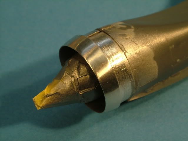
One more final check was in order to ensure nothing was getting pushed out of whack.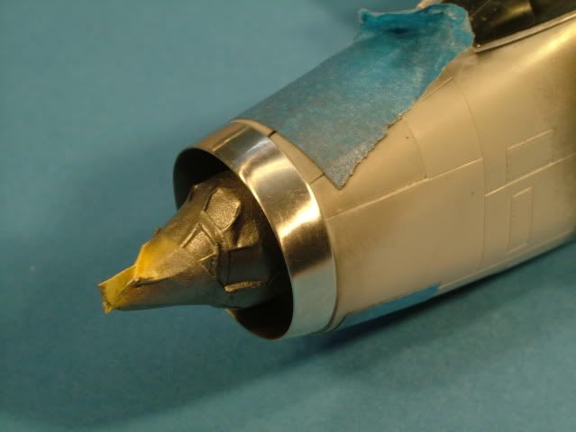
Some gentle sanding around the plastic nose frame ensured a nice fit.
Quite a bit of fiddeling was necesary and dryfitting before the wheelbay, nosecone all fell into place.
Vertical fin has been glued on, Horizontal stabilizers are just press fit.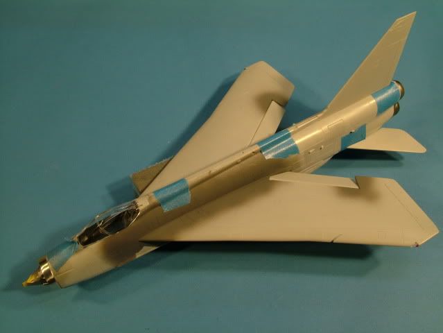
One side of the intake assembly has now been glued to the fuse half.
Tack glued at first, then another check with the opposite half in place,
Once satisfied, glued all around to ensure no movement can occur.
You will also notice I have glued in place a piece of white plastic card
around the nose intake ring and the air intake it self. This is to ensure this join can not fail and break apart.
I slightly sanded it to shape and doubles as a spacer to keep the whole assembly centered,
As well as slightly pushing out the sides of the nose to a more scale like
transition from the "cheeks" of the exterior to the nose lip.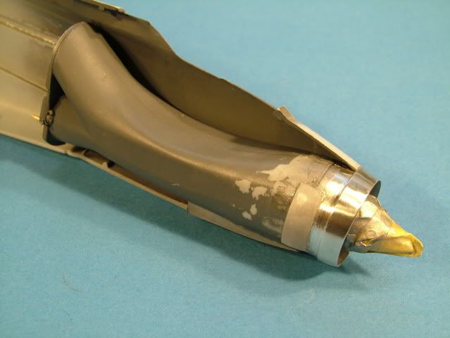
Seam Check.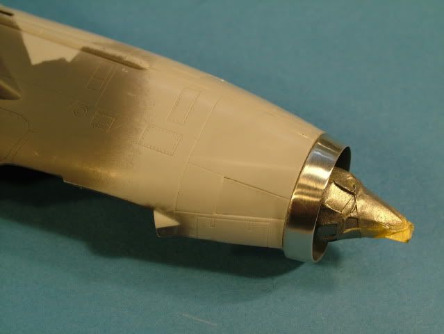
Some more lead solder was placed inside just to make sure.
I checked at the balance point and don't beleive this is necesary when using the Aeroclub weighted ring.
Thing is; it is better to be safe than sorry.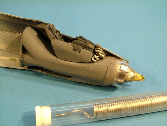
Fuselage was glued together with slow/thick super glue and spot glued with Tamiya Thin.
Once aligned and convinced the panel lines lined up from fuse side to fuse side, glued the complete seam with Tamiya Thin cement.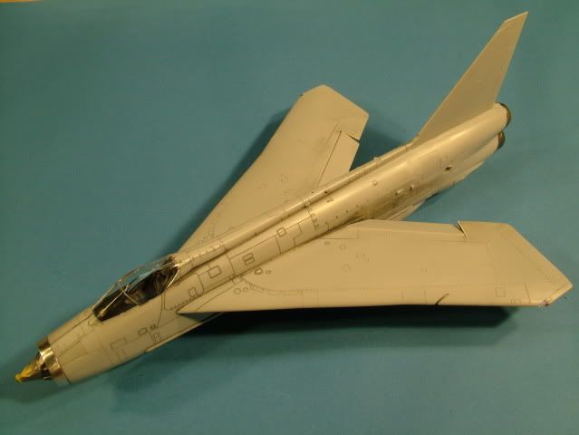
One last check with the cockpit glass to make sure all is aligned.
The fuse glue seam, will now need to harden overnight.
Next step is to checking all glue work, sanding and re-scribing where required. Some filler around the nose cone join, sand and fill.
The panel lines are highlighted with some Tamiya paint that was rubbed in with a paper towel and some X-20A thinner.
This method assists me in making sure, "as little as possible" damage to the panel lines, while sanding as they are easier to spot and see.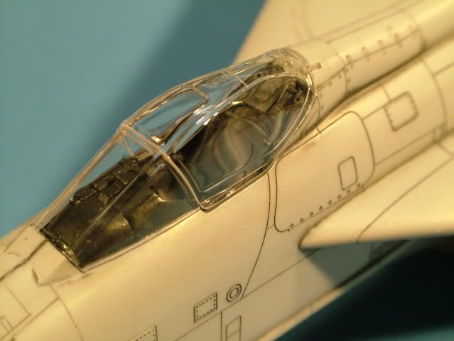
Belly fins glued on with Tamiya Thin cement.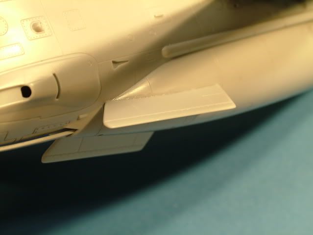
Small extra touch detail to the fin.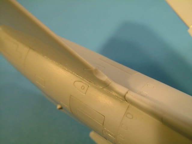
Using suitable small pin drill, drilled out the fin intake.
A nice little touch of extra detail.
Started to add one more "small" detail to the nose as well.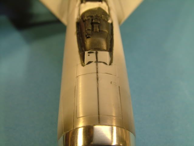
Found a reference picture which shows a small squared " box like " protrusion.
A small piece of white plastic card does the trick to simulate.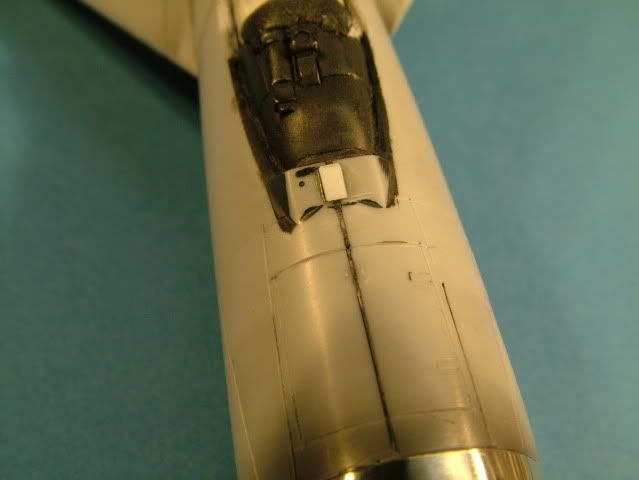
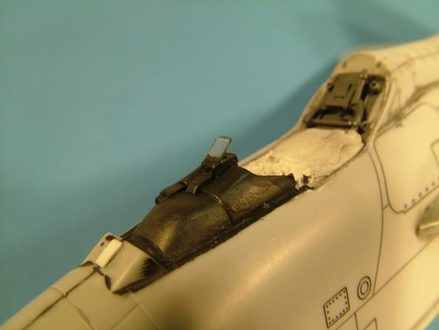
A small dollop of Model Master Metalizer Silver was applied for the track ball,
then once dry a small dollop of Tamiya Clear Green to simulate the glass aperature.
The HUD has been installed with the included clear acetate sheet from Aires.
A thin black edge was painted around to make it stand out a little as a frame.
Canopy masked off with some Kabuki Tape using a brand new blade following the canopy frame, then glued to the model with Gator Glue.
The model was wiped clean from finger prints and anti static treatment with Poly Scale Plastic Prep.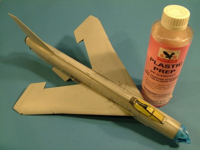
The Canopy Frame was painted with Tamiya Flat Black (XF-1).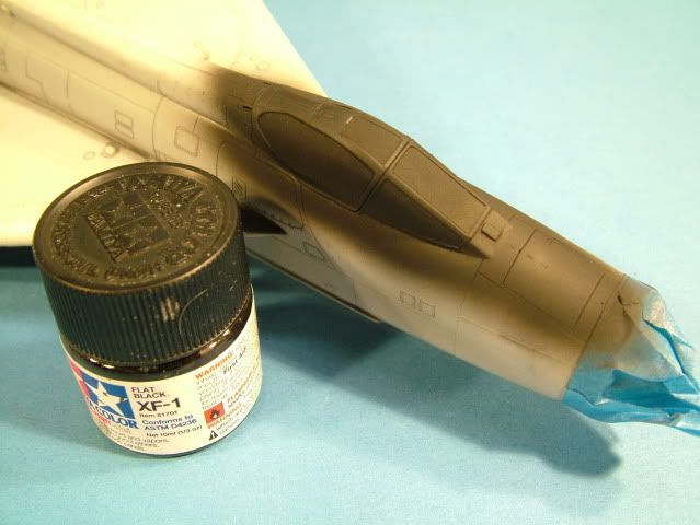
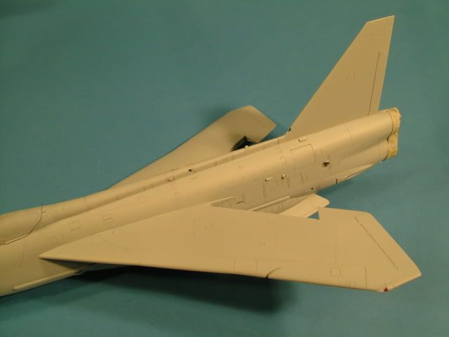
Mr. Surfacer 1200 treatment has been completed. Did some minor re-scribing on the belly and some riveting to provide a little bit more detail.
Cleaned up some small area's around the front armored cockpit glass to get as much of a near perfect fit as possible, used some Tamiya paint to "putty" then a light re scribe with a new Xacto blade.
A couple sink marks and the locating holes for the in flight fuel probe were spot treated with Mr. Surfacer 1000 putty and sanded down/blended.
Then another light light coat over the belly to blend it all in.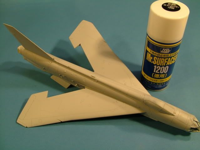
The gear wells are stuffed with "White Tack", as discussed on other threads,
White Tack does not leave behind any oily residue as Blue Tack tends to do.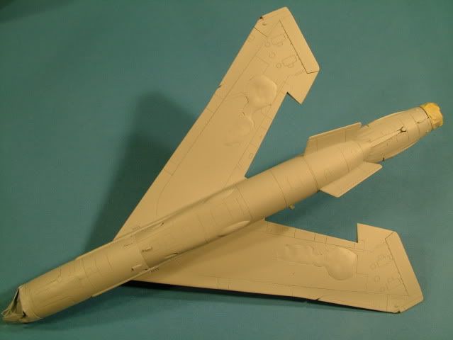
Painting time. Marcus was so kind to chase the builder at Britmodeller.com and find out which paint line and colors he used.
Yesterday I picked up the associated bottles of Mr Gunze:
#314 Blue FS35622
#21 Middle Stone
#22 Dark Earth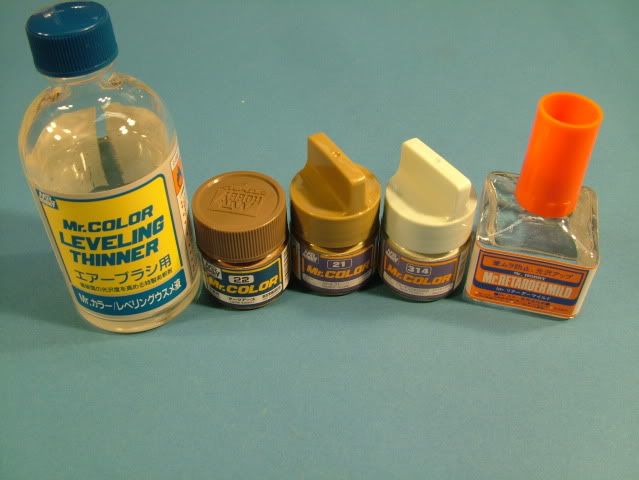
Pre-shading performed with Tamiya Flat Black XF-1.
Pressure at 10 psi, 60/40 Thinner to paint mix.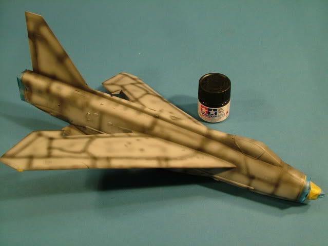
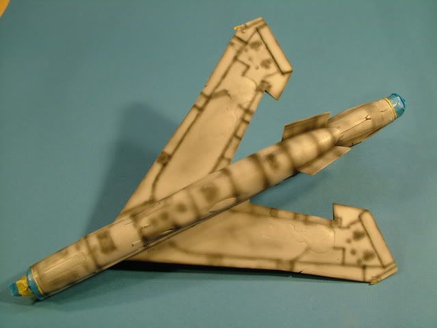
Underside has received 1 very light dusting, let dry, then a fill in coat on center of panels.
Last coat was a light wet coat overall to blend in.
Pressure at 8 psi, 60/40 Thinner to Paint and 12 drops of retarder to allow
for a good leveling action.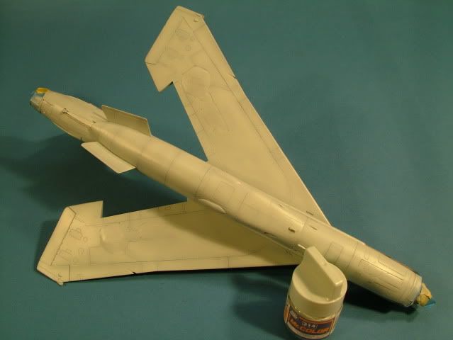
Very hard to discern on the pictures and lighting, but quite happy with the
pre-shading and post modulation of the paint on the center panels.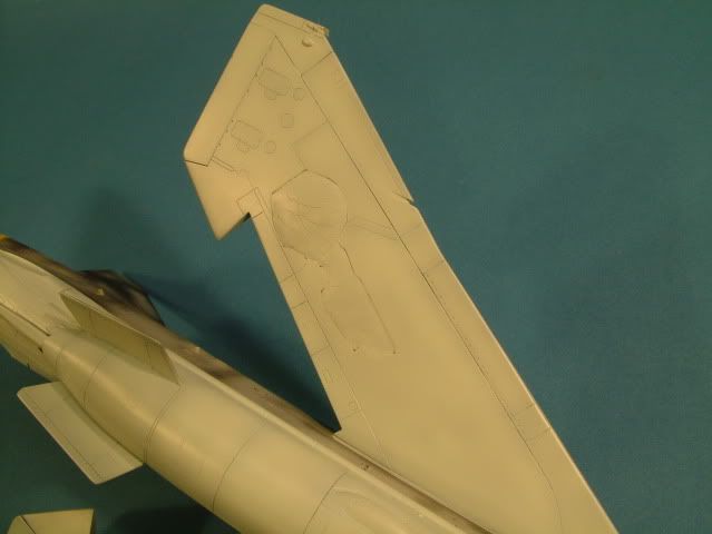
Middle Stone first passes, using the side profiles from the decal sheet,
traced the known pattern with a pencil, then filled in lightly.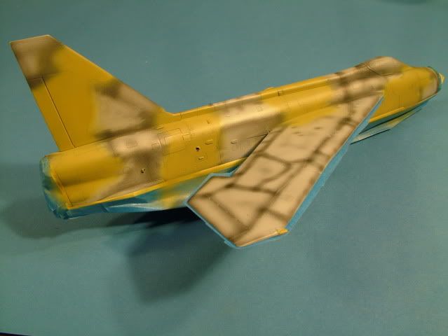
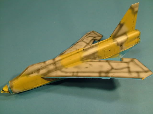
In order to get a feel for the top pattern (there are no known references)
Used a soft pencil and traced out something to my linking.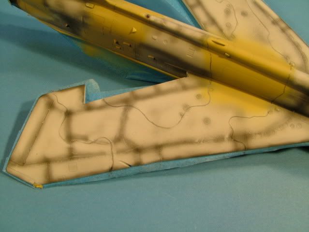
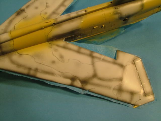
The "Middle Stone" color has now been applied, again starting from the center of the color area, working outwards, filling in.
A light coat first, then a concentration to highlight, then an overall wet coat to blend in.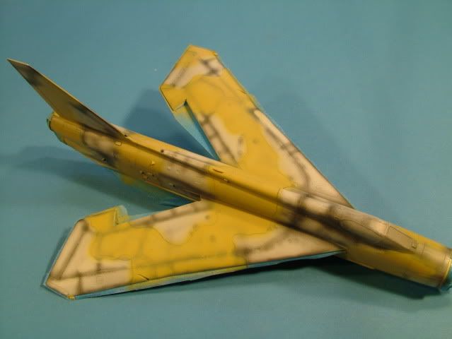
The pattern is quite intricate, using some "clear" frisket paper traced the pattern with a thin Red Sharpie.
Pulled it off the model, placed the Frisket paper on a glass plate cut it with a brand new blade.
Then re-applied back to the model, ready for painting.
Start of the "Dark Earth"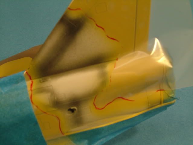
Most of the Dark Earth has been applied.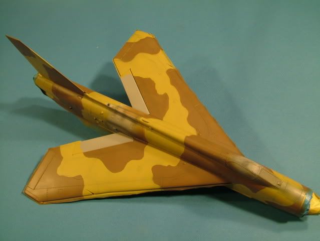
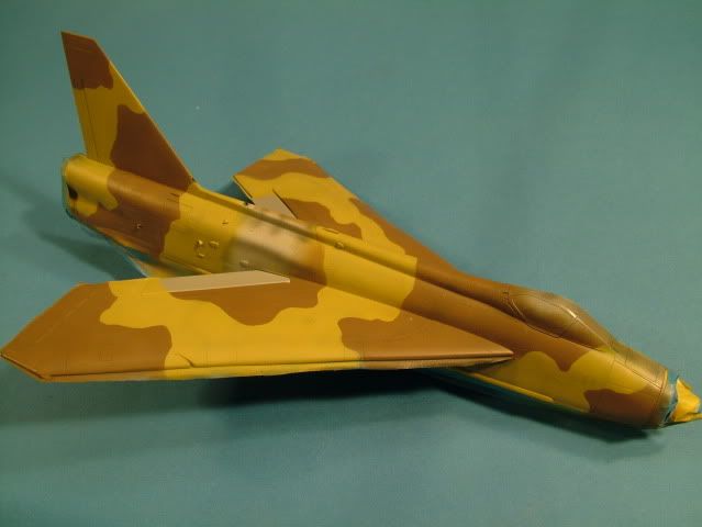
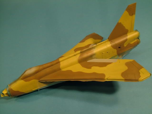
The process of eye balling the side profiles then matching up with the unknown top pattern, then transferring to frisket to get a good match,
and sharp demarcation is taking quite a bit of time.
Additionally spending some time to let the first coat dry, before filling in with highlights to ensure I do not over do it and loose the pre-shading.
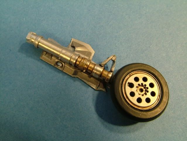
Worked the SAC white metal landing gear.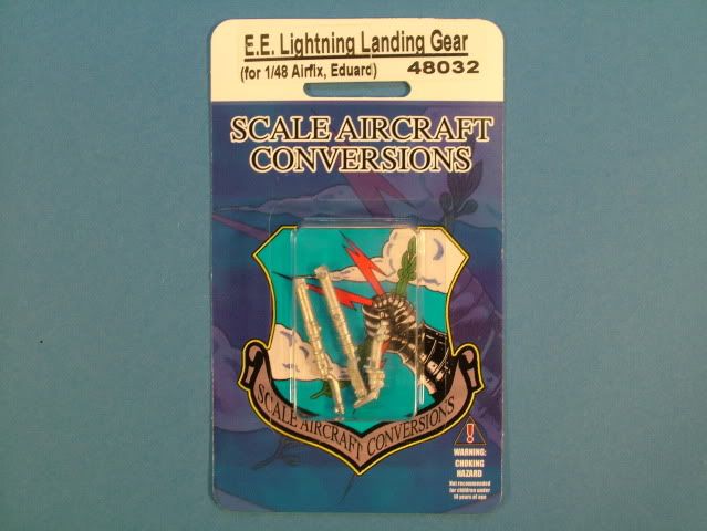
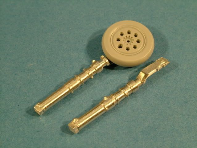
Used some soft wire from Plus Model to make a break-line, painted with Tamiya X-1 Gloss Black. 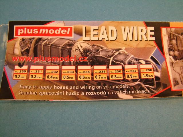
The break-line is held in place with some very thin strips of Tamiya tape.
The tape was painted with some Model Master Plate Silver to match the gear.
The gear was then given a light oil wash, made with Winston Oils;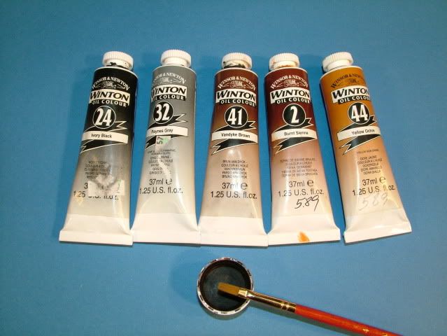
Ivory Black and Burnt Sienna (30 Black/70 Sienna) was used this time with 80% oderless thinners to the oil paint mixture.
It was left to dry for 5 minutes then wiped clean with a cotton bud, lightly wetted with some Tamiya thinner X-20.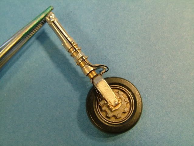
One gear door installed.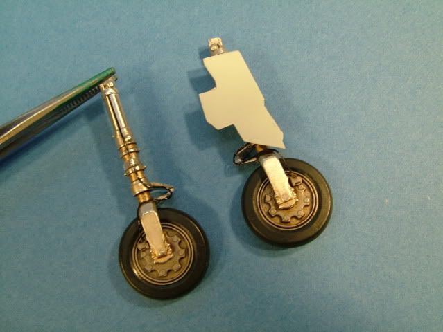
Used some little lenses from Little Cars to dress up the landing lights.
Drilled out the resin light and inserted the little lens, glued with some thick super glue.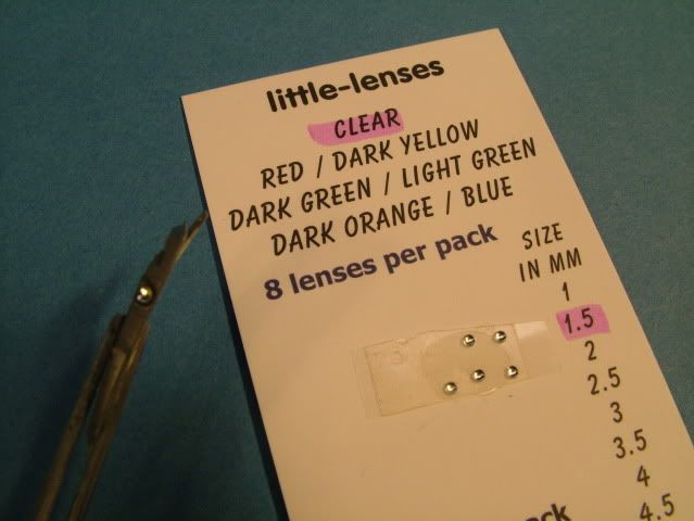
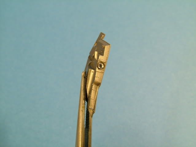
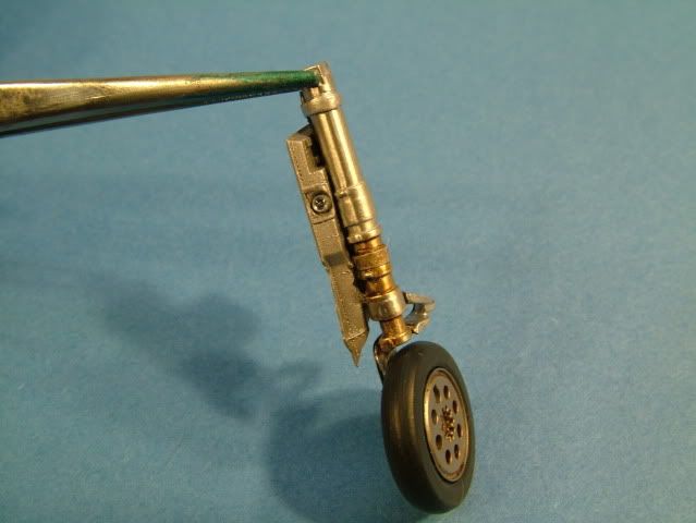
Nose gear ready for installation.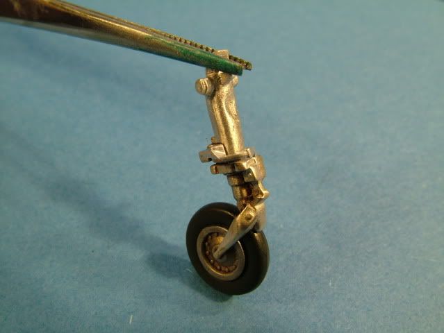
Elevators finalized.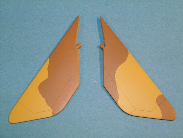
Canopy painted black and the anti dazzle area.
Elevators glued on.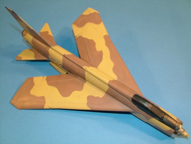
Camouflage pattern all finished and cleaned up at the edges.
Lightly polished all around the demarcation area's with 12000 grit sanding sponges and some distilled water.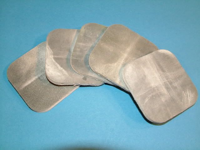
This ensures there is smooth transition from paint color to paint color.
As such no ridges due to paint build up that might have occured where it was masked.
Also the Black fin tip has been completed.
Model Master Clear Coat applied at 10 PSI, 60/40 Thinner/paint mix, starting out with light dusty coats.
Slowely building up the volume overall to get a nice smooth Gloss finish.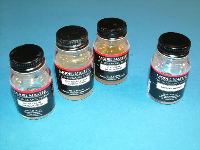
in preparation of the decalling stage.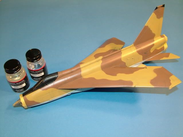
Decalling Stage:
There are going to be quite a few decals applied.
Given that I will be using some from:
- The original Airfix Kit,
- The Model Alliance sheet provides the Saudi Scheme (roundels) and squadron markings
- Plus the stencils from the Baracuda Cals sheet.
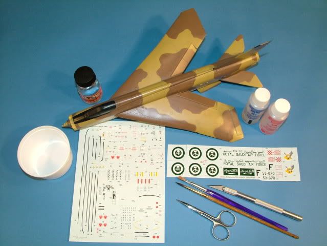
Some of the usefull tools to have handy.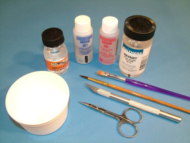
I have resurected these notes from one of my earlier builds and amended with some additional handy ones, as I dicover them and pass them along (we start at step 7)
A consolidated stepped approach to that Painted on Look of Decals:
After a few hours here are the results.....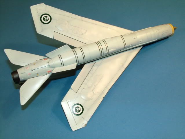
A lot of time was spent on ensuring the belly black lines were all parrallel. 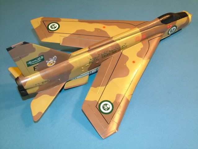
As well as piece mealing together the black walk way lines on the top.
As there are no know references of this scheme (Top) it is just my interpretation these would have been painted back on,
eventhough this was an evaluation scheme.
A not foreseen difficulty was the fact that the Saudi Roundel's placement is different from the standard British roundels
as well as the fact that these are quite a bit smaller in diameter.
This resulted in having to use a couple small black lines from the Airfix kit to piece together the full length of walkway.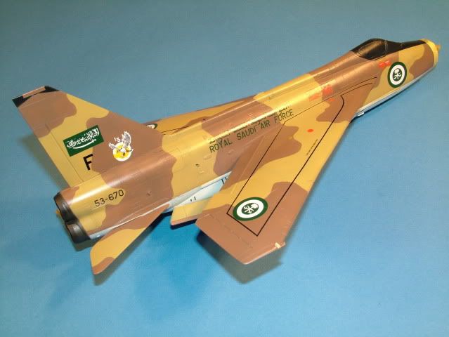
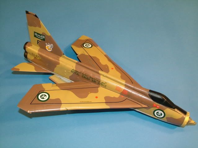
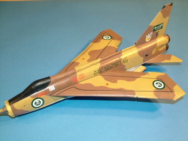
Onward with Steps 18 through 21
-
Gloss Clear coat (paint or Future) - let Future dry for 24 hrs (this step literally seals-in the decals and protects them from any harm on the following detailing steps, and makes the colorless carying film on the outer edges disapear into the prior applied gloss coat.
-
Promodeller wash and weathering powders, pin washes and stains are now applied depending on the effect you want to achieve
-
Gloss Clear coat Paint or Future - let Future dry for 24 hrs OR
-
Final Clear coat, (Flat or Semi Gloss) pending the requirement
ProModeller Wash on to the Top surfaces a blend of Black and Dark Dirt.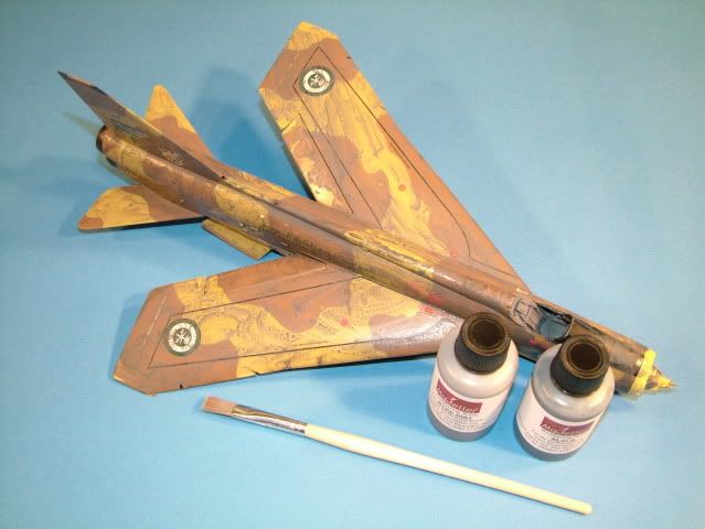
Bottom only Dark Dirt.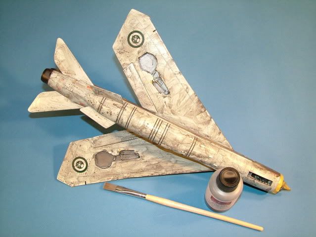
Once the wash is removed a Super Flat coat was applied in two coatings. Using Model Master Flat.
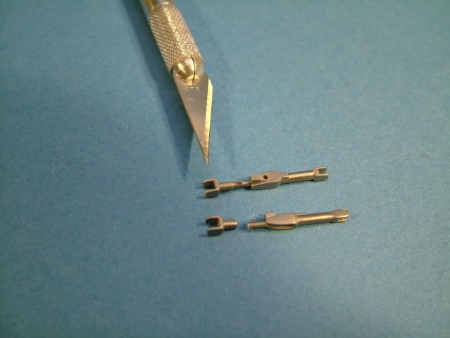
A small modification is necessary to the Actuator Arm, by cutting off the connector and moving it a quarter turn.
Not sure why Airfix has them molded this way, but to properly align them into the door slot
and hooking it up to the actuator pin in the wheel well this is required.
Reference picture of the Landing Gear Actuator Arm.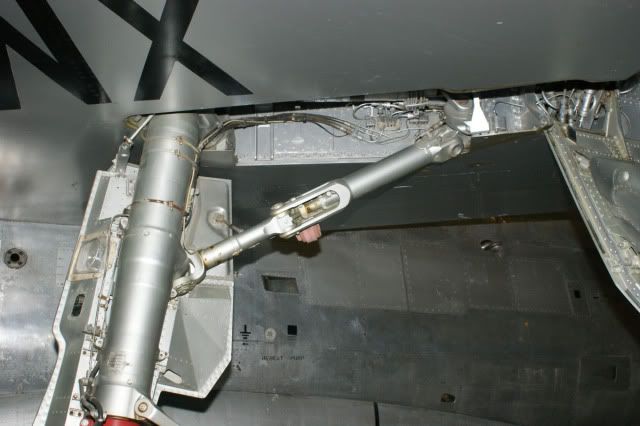
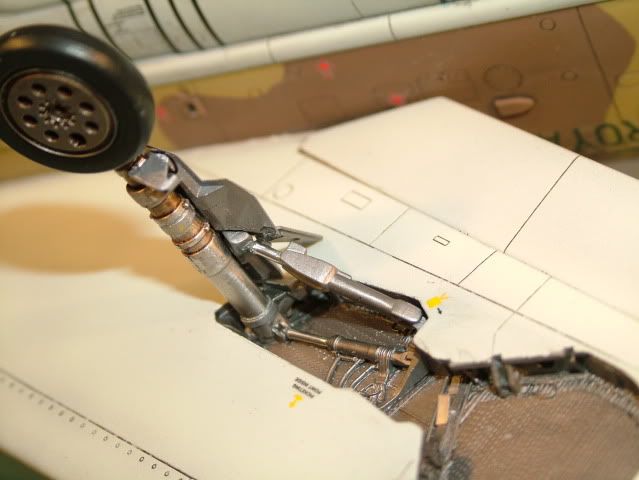
Applied a thin pin wash with orderless Thinner and some Burnt Sienna plus Ivory Black Oil Paint into the wheel wells.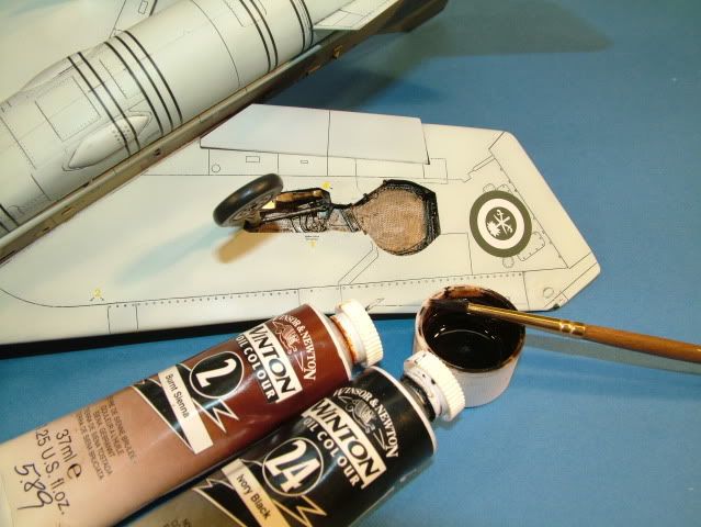
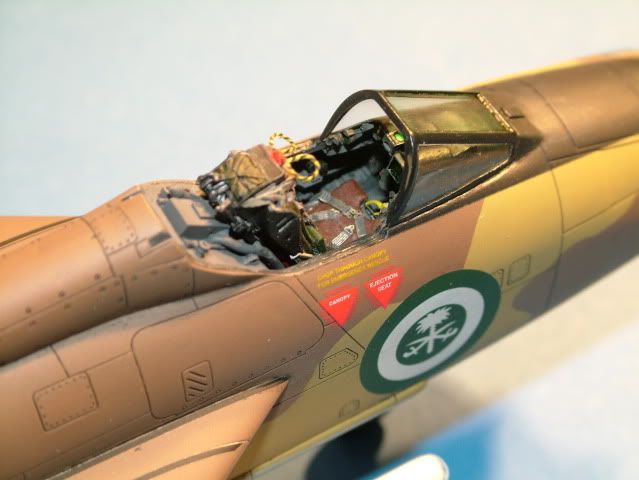
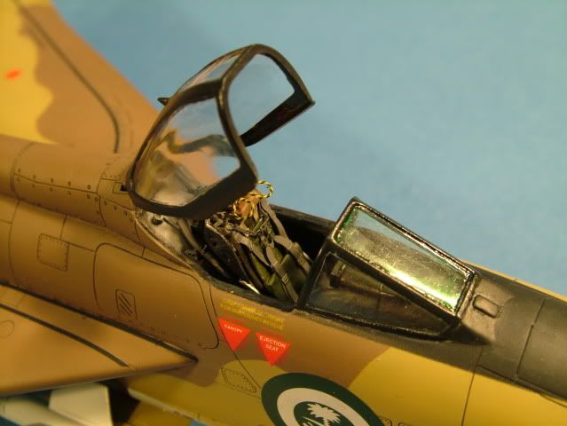
Tamiya Clear Green simulates the armored front cockpit glass.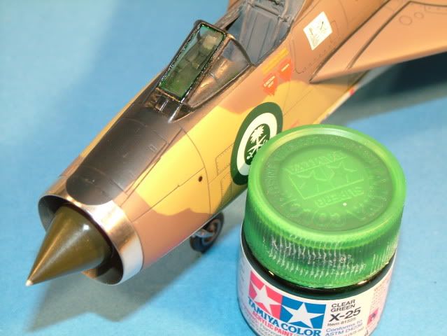
Built up the missiles and the missile rails.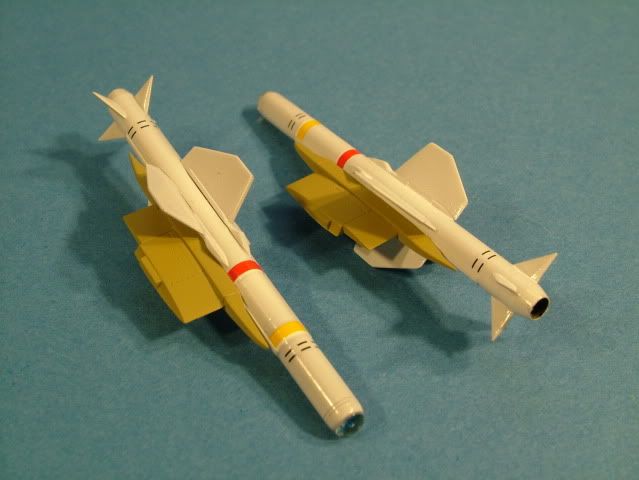
Front glass of the seaker heads were drilled out and applied a thin coating of Tamiya Clear Blue.
Finished the lap belts and installed the EJ seat.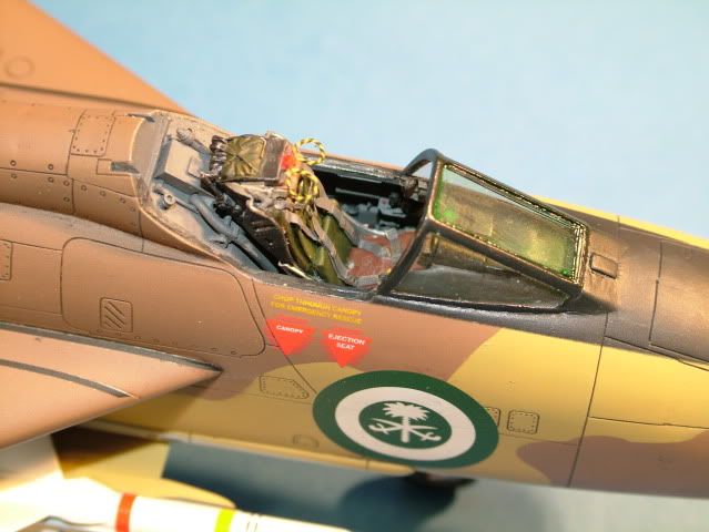
Nose Gear reference picture.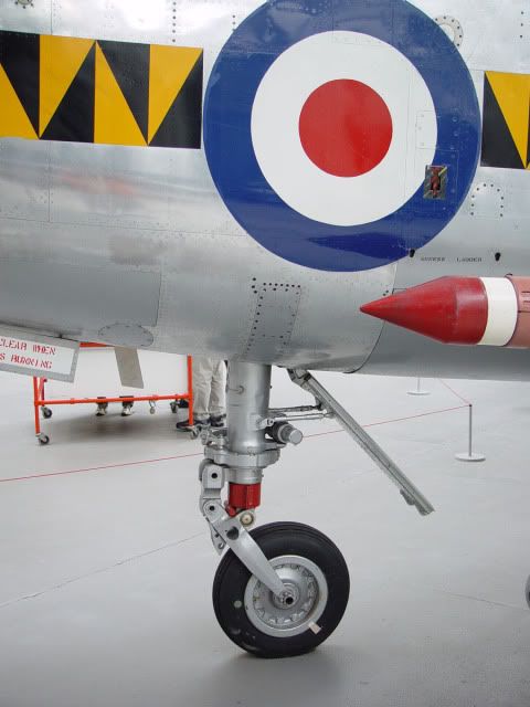
Installed the Nose Gear door and installed two small brass rods to simulate the actuators.
Didn't quite get the same angle, I beleive the resin door is a touch too tall.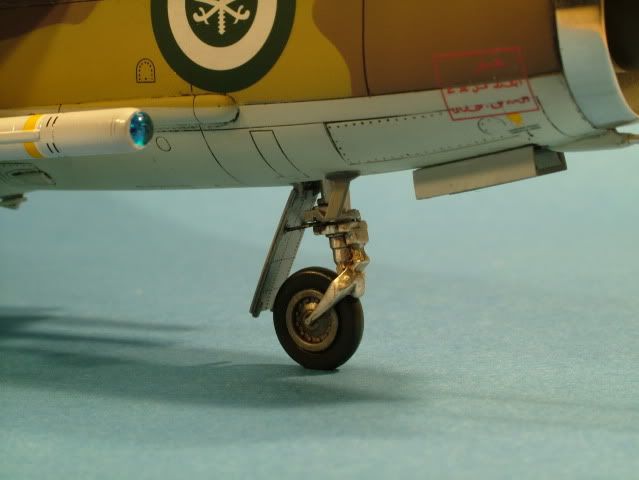
Main Landing Gear reference pictures.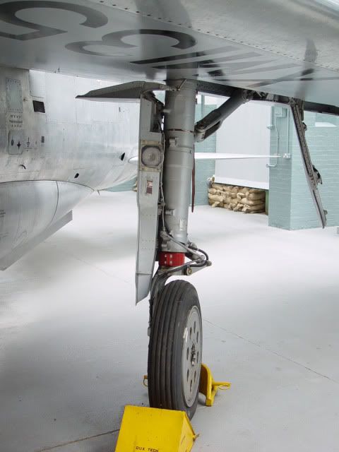
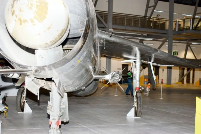
Notice that the main legs are straight up and down and the main wheel doors slightly angle outward.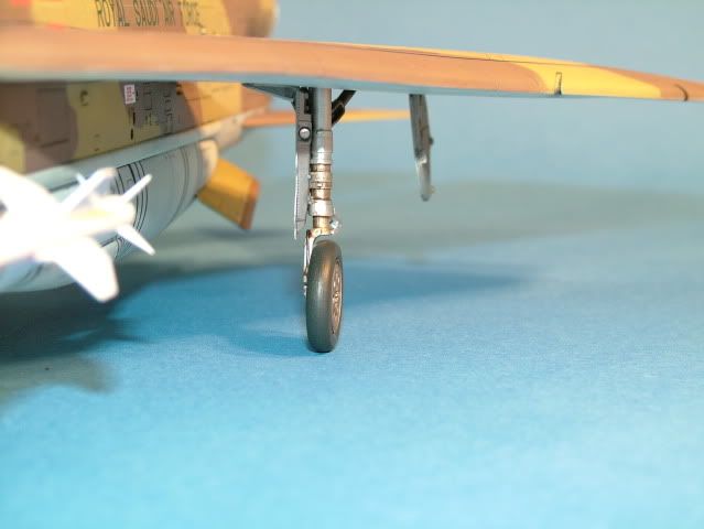
Forward cant of the main gear.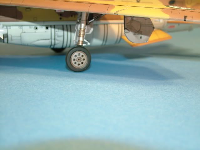
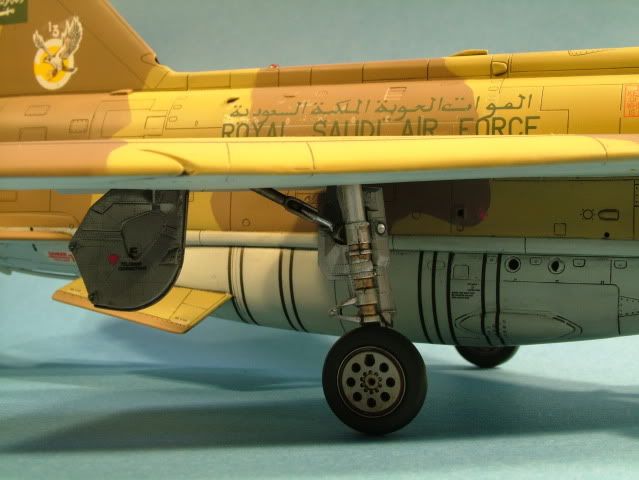
Last small bits placed on the model where an antenna under the nose and the pitot tube.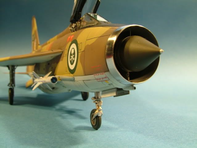
Completed model pictures: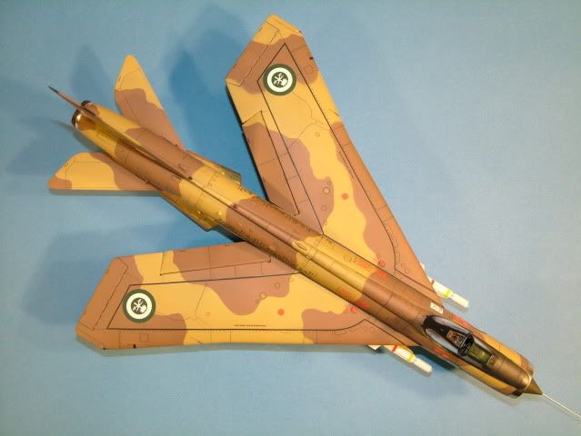
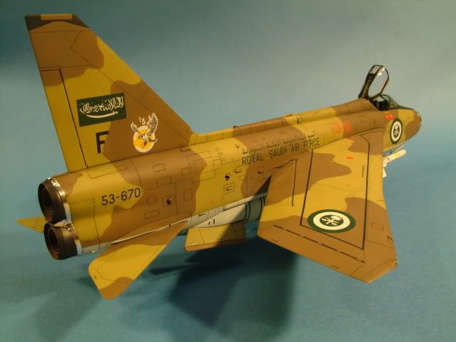
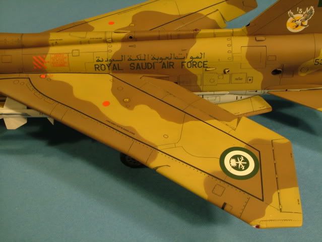
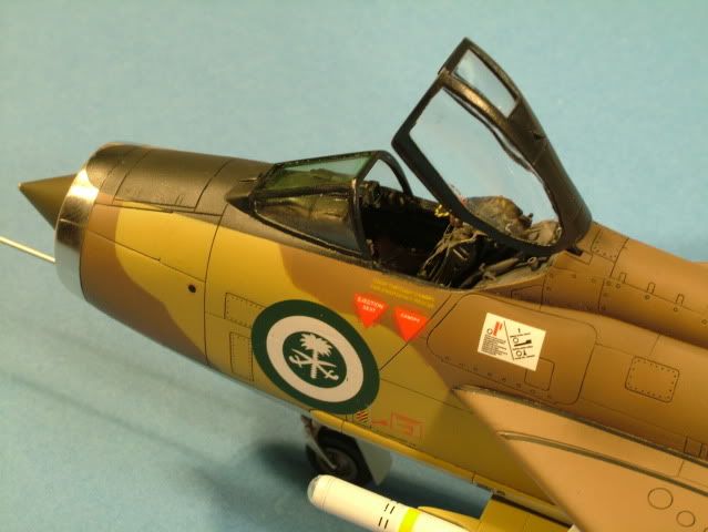
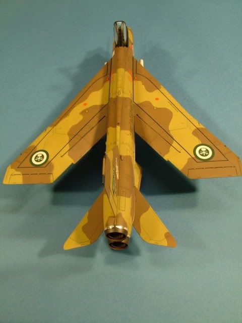
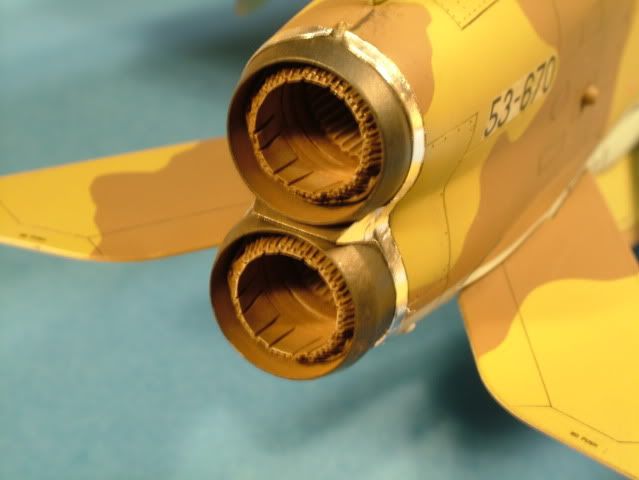
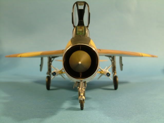
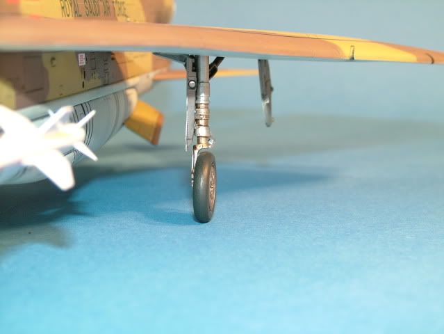
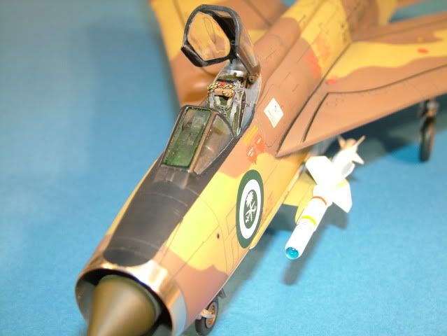
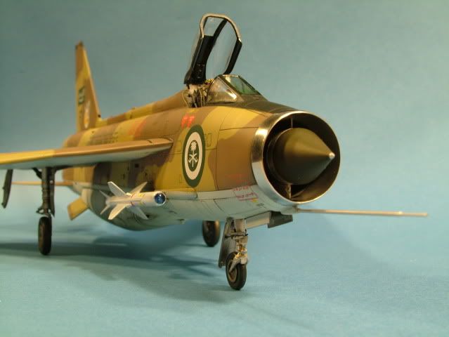

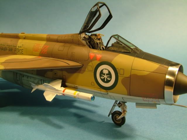
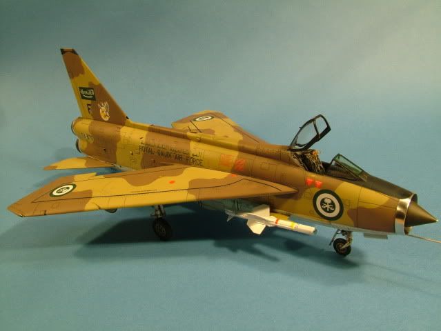
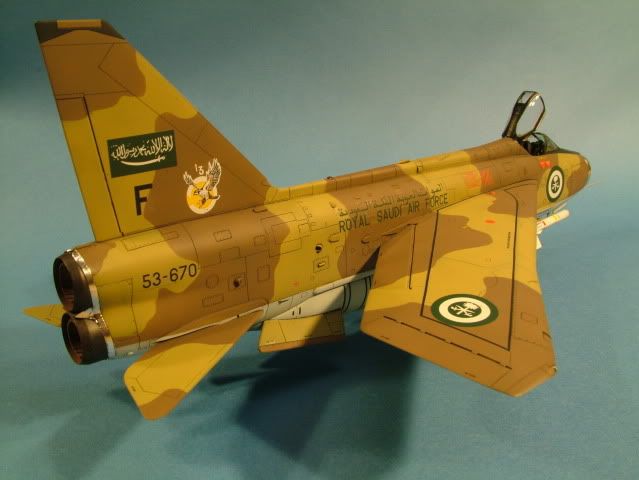
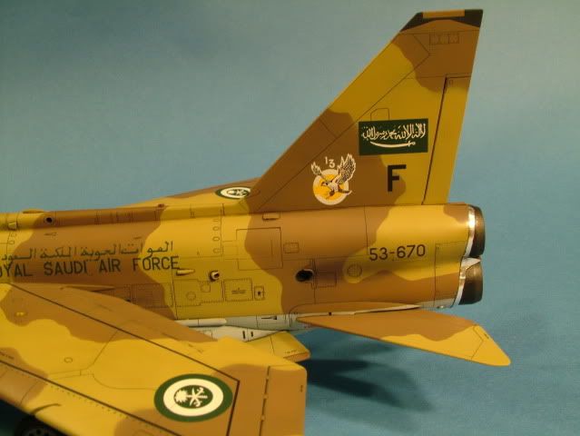
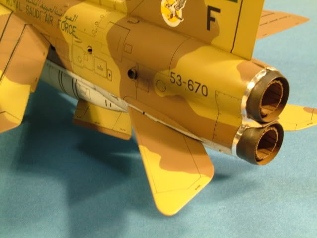
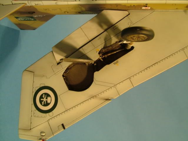
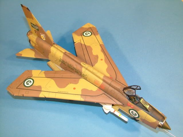
Thoroughly enjoyed the challenge of this kit with all the Aires aftermarket parts and the unusual evaluation scheme
make for a unique addition to my cold war era jet collection.
See you soon on my next build.
-
Prep plastic with Squadron's "Plastic prep" or wash model with dish washing soap. This will assist with removing dust - finger prints and makes plastic anti - static
-
Start using a rubber "doctors glove" when handeling the model from this point forward as not to induce finger prints "again". Primer Coat
-
Pre-shading
-
Top Coat of whichever camo. Note: When working with an NMF paint job, now is the time to switch to using your "white" coton glove, instead of the rubber glove.
-
Post Shading
-
Gloss Clear Coat (paint or Future) - let Future dry for 24 hrs
-
Apply Decals,
-
Prepare a shallow dish with some luke warm distilled water and about 10 drops of Micro Sol.
-
Cut out each individual marking as needed using some small cuticle scissors.
-
Submerge the decal into the solution for about 2 minutes, holding by an edge with some self locking tweezers.
-
Remove from water and check to see if decal moves freely with finger (do not force).
-
Apply some Micro Set to the area where decal will be placed.
-
Slide decal from backing paper onto the model with a stiff brush and move to required position,
-
Check references (photos and decal sheet) continuously/read panel lines and other items such as antenas, to reference from.
-
-
Remove excess water with a kitchen towel (blotting), then press down with cotton bud (rolling motion) - let dry for 4 hrs.
-
Then apply Micro Sol/Set pending the need and decals had a chance to adhere a little - let dry for 8 hrs
-
If needed go back and re-apply Micro Set to any stubborn decals.
-
Also use a brand new blade and cut carefuly through the decals where they cross over panel lines, then apply a little Micro Set.
-
This will assist in making it look even more painted on as in real life an insignia etc. would most likely not "span" across a hinged area or panel, rather "disapear" to the eye into the two ajoining surfaces.
-
Another trick at this stage is to prick any small trapped air bubles that are visible (silvering) with a needle and let some Micro Set or Sol work into the small pricked hole.
-
This is an especialy critical step when large areas of the decal you are applying has a "clear" section, like the center of a zero or the "holes" of an "8" for instance.
-
-
Remove any hard water spots with some distilled water and a cotton bud.
-
Gloss Clear coat (paint or Future) - let Future dry for 24 hrs (this step literally seals-in the decals and protects them from any harm on the following detailing steps, and makes the colorless carying film on the outer edges disapear into the prior applied gloss coat.
-
Promodeller wash and weathering powders, pin washes and stains are now applied depending on the effect you want to achieve
-
Gloss Clear coat Paint or Future - let Future dry for 24 hrs OR
-
Final Clear coat, (Flat or Semi Gloss) pending the requirement
